Supercharge Your Innovation With Domain-Expert AI Agents!

A kind of preparation method of thermal spraying ceramic coating with high anti-wear and low friction coefficient

A low friction coefficient, ceramic coating technology, applied in the coating, metal material coating process, fusion spraying and other directions, can solve the problems of the ceramic coating tribological properties can not be greatly improved, the effect is not very obvious, etc. Achieve the effect of low friction coefficient and wear rate, excellent friction characteristics, and improved wear life

Active Publication Date: 2019-01-04
LANZHOU INST OF CHEM PHYSICS CHINESE ACAD OF SCI
View PDF4 Cites 1 Cited by
  • Summary
  • Abstract
  • Description
  • Claims
  • Application Information

AI Technical Summary

Problems solved by technology

[0003] Ceramic coatings prepared by thermal spraying are mostly used as wear-resistant coatings for key components in high-tech fields, such as Al 2 o 3 、Al 2 o 3 -TiO 2 、Cr 2 o 3 Ceramic coatings such as ceramics have played an important role in various mechanical moving parts in terms of adhesion resistance, fretting resistance, erosion resistance, and abrasive wear resistance, and have been widely used. However, due to the inherent characteristics of ceramic materials, the ceramic coating The tribological properties of Al 2 o 3 The friction coefficient of the base coating at room temperature is about 0.5~0.6, and the wear amount is 10 -4 ~10 -5 μm / N·mm 3 between
In order to improve the friction and wear properties of thermal sprayed ceramic coatings, powders with lubricating properties, such as Ag, MoS 2 , BN, graphite, etc. Although the tribological properties of the obtained composite coating have been improved, the effect is not very obvious

Method used


Image

  • A kind of preparation method of thermal spraying ceramic coating with high anti-wear and low friction coefficient
  • A kind of preparation method of thermal spraying ceramic coating with high anti-wear and low friction coefficient
  • A kind of preparation method of thermal spraying ceramic coating with high anti-wear and low friction coefficient

Examples


Embodiment 1

[0022] A: The surface of the 1Cr18Ni9Ti stainless steel substrate is roughened and cleaned, and then placed on the spraying table. Using atmospheric plasma spraying equipment, the NiAl transitional coating and Al are sprayed on the stainless steel substrate. 2 o 3 Ceramic coating, Al 2 o 3 The thickness of the ceramic coating is about 270 μm; then the surface of the ceramic coating is ground and polished, and the surface roughness Ra≈1.6 μm.

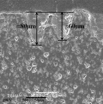
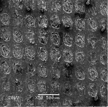
[0023] B: the Al prepared in step A 2 o 3 The ceramic coating is placed on a laser texturing table to prepare surface micropores. The prepared micropores have a diameter of about 230 μm to 280 μm and a pore depth of about 50 μm to 70 μm. 32%, and the spacing between the holes is basically the same.

[0024] C: the Al prepared in step B 2 o 3 The ceramic coating was vacuum impregnated (vacuum: -0.72 bar) for 4 hours after soaking in a PTFE emulsion with a solid content of 60%.

[0025] D: Take out the coating completed in step C f...

Embodiment 2

[0031] A: The surface of the 7075 aluminum alloy substrate is roughened and cleaned, then placed on the spraying table, and the NiAl transition coating and Al are sprayed on the aluminum alloy substrate by using atmospheric plasma spraying equipment. 2 o 3 Ceramic coating, Al 2 o 3 The thickness of the ceramic coating is about 180 μm; then the surface of the ceramic coating is ground and polished, and the surface roughness Ra≈1.4 μm.

[0032] B: the Al prepared in step A 2 o 3 The ceramic coating is placed on a laser texturing table to prepare surface micropores. The prepared micropores have a diameter of about 240 μm to 260 μm and a pore depth of about 60 μm to 80 μm. 35%, and the spacing between the holes is basically the same.

[0033] C: the Al prepared in step B 2 o 3 The ceramic coating was vacuum impregnated (vacuum: -0.74 bar) for 6 hours after soaking in PTFE emulsion with 50% solids content.

[0034]D: Take the coating completed in step C out of the PTFE emul...

Embodiment 3

[0040] A: The surface of the GH 4169 substrate is roughened and cleaned and placed on the spraying table, and the NiAl transitional coating and Al are sprayed on the GH 4169 substrate by using atmospheric plasma spraying equipment. 2 o 3 Ceramic coating, Al 2 o 3 The thickness of the ceramic coating is about 300 μm; then the surface of the ceramic coating is ground and polished, and its surface roughness is Ra≈0.8 μm.

[0041] B: the Al prepared in step A 2 o 3 The ceramic coating is placed on a laser texturing table to prepare surface micropores. The prepared micropores have a diameter of about 220 μm to 270 μm and a pore depth of about 55 μm to 74 μm. 40%, and the spacing between the holes is basically the same.

[0042] C: the Al prepared in step B 2 o 3 The ceramic coating was vacuum impregnated (vacuum: -0.79 bar) for 5 hours after soaking in PTFE emulsion with a solid content of 55%.

[0043] D: Take the coating completed in step C out of the PTFE emulsion, put i...


PUM

PropertyMeasurementUnit
Thicknessaaaaaaaaaa
Surface roughnessaaaaaaaaaa
Pore diameteraaaaaaaaaa

Abstract

The invention discloses a preparation method of a high-wear-resistance and low-friction-coefficient thermal spraying ceramic coating layer. The high-wear-resistance and low-friction-coefficient thermal spraying ceramic coating layer, prepared on a metal base material by a thermal spraying technology, adopts three combined processes of atmosphere plasma spraying, laser surface microhole texturing and vacuum dipping, that is, the preparation of the ceramic coating layer is finished by atmosphere plasma spraying; the microhole texturing on the surface of the coating layer is automatically finished by a laser; the total area of microhole areas in surface texturing is about 30-40% of total area of the surface of the coating layer; permeation of polytetrafluoroethylene (PTFE) lubricant on the surface of the coating layer is finished by the vacuum dipping method; and finally, the coating layer is obtained by leveling the surface of the ceramic coating layer. Compared with other ceramic coating layers, the obtained ceramic coating layer is lower in friction coefficient and wear rate, and largely prolongs the wear resisting life.

Description

technical field [0001] The invention relates to a method for preparing a thermal spray ceramic coating with high wear resistance and low friction coefficient, and belongs to the technical field of coating surface modification. Background technique [0002] The ionic bond and covalent bond structure of ceramic materials have high bond energy, strong interatomic bonding, low surface free energy, small atomic distance, dense packing, and no free electron movement. These characteristics endow ceramic materials with high melting point and high hardness. , high chemical stability, high insulation and heat insulation and no ductility and other excellent characteristics. The use of thermal spraying technology to prepare ceramic coatings can endow metal surfaces with incomparable excellent properties of many metal materials, so this process technology has developed rapidly, and various types of ceramic coatings prepared have played an increasingly important role in the industrial fie...

Claims


Application Information

Patent Timeline
IPC IPC(8): C23C4/18C23C4/134C23C4/11C04B35/10C04B35/622
CPCC04B35/10C04B35/62222C23C4/18
Inventor 安宇龙李双建赵晓琴侯国梁周惠娣陈建敏
Owner LANZHOU INST OF CHEM PHYSICS CHINESE ACAD OF SCI
Features
  • R&D
  • Intellectual Property
  • Life Sciences
  • Materials
  • Tech Scout
  • Unparalleled Data Quality
  • Higher Quality Content
  • 60% Fewer Hallucinations
Learn More