Nanorod-based fluorescence enhancement structure, nanorod-based fluorescence detection system and autoinjection detection chip

A fluorescence enhancement and detection chip technology, which is applied in the field of detection and analysis, can solve the problems of complex operation steps, complex detection process, and low detection sensitivity, and achieve the effects of good specificity, simple manufacturing method, and high parallelism

Inactive Publication Date: 2018-08-10
ZHEJIANG UNIV +1
View PDF3 Cites 5 Cited by
  • Summary
  • Abstract
  • Description
  • Claims
  • Application Information

AI Technical Summary

Problems solved by technology

[0011] Aiming at the shortcomings of low detection sensitivity and complicated detection process in traditional fluorescence immunoassay, the present invention proposes a biological detection system based on the fluorescence enhancement effect of nanostructures, which is used for high-sensitivity detection of biomolecules such as proteins and DNA, and provides nanostructured simple manufacturing method
Through the combination of nanostructure and microfluidic chip, the present invention solves the disadvantages of complex operation steps, low detection sensitivity, and large background noise in fluorescence immunoassay, and realizes ultrasensitive detection of biomarkers, thereby realizing early diagnosis of diseases

Method used


Image

  • Nanorod-based fluorescence enhancement structure, nanorod-based fluorescence detection system and autoinjection detection chip
  • Nanorod-based fluorescence enhancement structure, nanorod-based fluorescence detection system and autoinjection detection chip
  • Nanorod-based fluorescence enhancement structure, nanorod-based fluorescence detection system and autoinjection detection chip

Examples


Embodiment 1

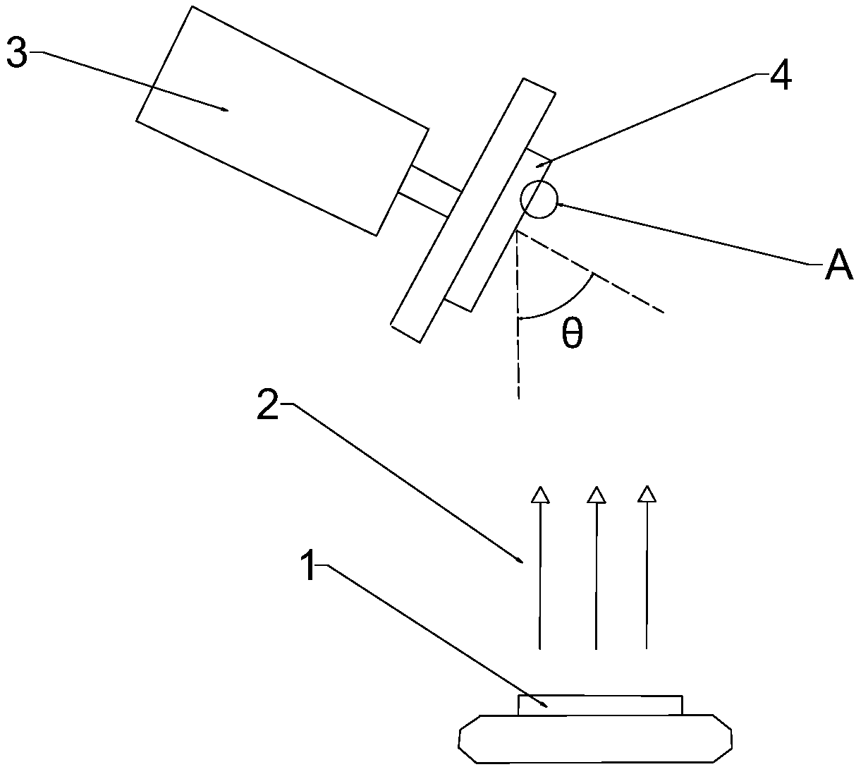
[0042] Preparation of Nanorods by Oblique Angle Deposition

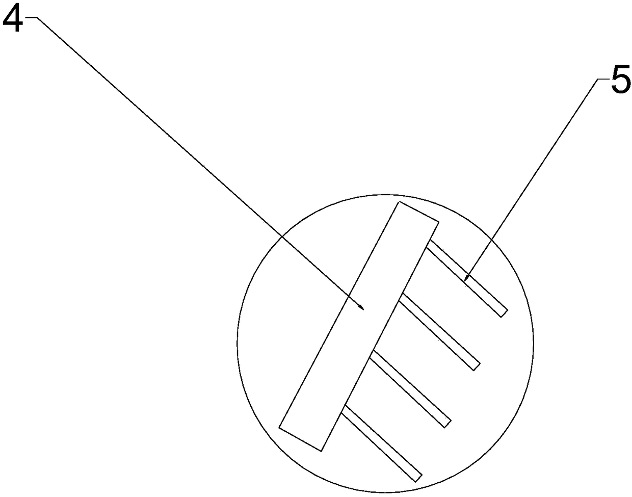
[0043] Such as figure 1 As shown, the raw material source 1 is placed in the crucible, the gun filament under the preparation device 3 emits electron beams, and the raw material source (gold, silver, silicon oxide, etc.) in the crucible is evaporated. The raw material source 1 forms a raw material vapor 2, and the normal direction of the glass plate substrate 4 of the preparation device forms an angle θ (evaporation angle) with the direction of the vapor. Finally, nanorods 5 are formed on the substrate 4 .

[0044] Vapor nucleates first on the substrate surface, and nucleation centers on these surfaces continue to grow into nanostructures due to limited surface atom diffusion and shadowing effects. The shape parameters of the nanostructure can be controlled by controlling the evaporation angle θ, the rotation speed of the substrate during deposition, the deposition thickness, the deposition rate, and the power, and...

Embodiment 2

[0047] A fluorescence enhancement experiment was performed on the gold nanorods obtained in Example 1, and a fluorescence enhancement coefficient curve of the nanostructure was obtained.

[0048] Cover the surface of the gold nanorods obtained in Experiment 1 and the surface of the glass sheet with the same concentration and volume of fluorescent solution, and analyze the fluorescence intensity using a fluorescence microscope, and the ratio is the fluorescence enhancement coefficient.

[0049] Specifically, a fluorescein solution with a concentration gradient of 1 pM-100 μM is prepared. Put the gold nanorods into the reaction chamber with the same volume, and the reaction chamber is prepared by PDMS bonding glass substrate and a cover glass is added on it. Add the same volume of fluorescein solution with different concentration gradients into the reaction chamber, take and analyze the fluorescence images with a microscope camera, and get Figure 4 Schematic diagram of fluores...

Embodiment 3

[0051] Detection of cardiovascular diseases with cTnI antibody modified on the surface of metal nanorods.

[0052] Troponin I (cTnI) is of great significance in the early diagnosis of cardiovascular. In this embodiment, nanostructures are used to detect cTnI with high sensitivity.

[0053] The specific operation steps are as follows: First, a layer of self-assembled film (DSP / DSU / PEG, etc.) is fixed on the surface of the metal nanostructure, and a layer of Protein A / G molecules (optional) is covered on the self-assembled film, and then BSA solution block is added. The monoclonal antibody of troponin I is immobilized on the surface of the nanostructure through Protein A / G molecules, and biological samples containing different concentrations of troponin I are added, and continue to bind to the polyclonal antibody of the molecule, and finally the fluorescently labeled secondary antibody binds The polyclonal antibody realizes quantitative analysis, and the concentration of troponi...


PUM

PropertyMeasurementUnit
thicknessaaaaaaaaaa
diameteraaaaaaaaaa
thicknessaaaaaaaaaa

Abstract

The invention provides a nanorod-based fluorescence enhancement structure, a nanorod-based fluorescence detection system and an autoinjection detection chip. The fluorescence enhancement structure comprises a substrate, a nanorod and an antibody or single-stranded DNA for modifying the nanorod, wherein the nanorod structure is prepared through tilted angle deposition on a substrate. The autoinjection detection chip has the advantages of realization of highly-sensitive, rapid and microfluidic autoinjection detection of a biomarker, simplicity in operation, and low cost.

Description

technical field [0001] The invention belongs to the field of detection and analysis, and relates to a fluorescence enhancement structure, a fluorescence detection system and an automatic sampling detection chip. Background technique [0002] Biomarkers provide indicators of human body function as well as predictive, diagnostic and prognostic information for disease. Detecting the concentration of biomarkers in biological samples (blood, saliva or urine, etc.) is of great significance for early diagnosis of diseases and personalized treatment. [0003] Existing detection methods include enzyme-linked immunosorbent assay (ELISA), fluorescent immunoassay (fluorescentimmunoassay), colorimetric analysis (colorimetric analysis) and so on. [0004] Enzyme-linked immunosorbent assay (ELISA) [0005] ELISA technology uses enzyme-labeled antibodies to specifically bind to a certain biomarker antigen adsorbed on a carrier. After the substrate solution is added dropwise, the hydrogen...

Claims


Application Information

Patent Timeline
Patent Type & Authority Applications(China)
IPC IPC(8): G01N21/64G01N33/68
Inventor 曹臻杨文婷陈亮赵炅东
Owner ZHEJIANG UNIV
Why Eureka
Try Eureka