Efficient low-resistance nano-fiber microscopic gradient structure filtering material and preparation method thereof

A technology of micro-nano fiber and gradient structure, applied in the direction of separation method, filtration separation, membrane filter, etc., can solve the problems of low filtration resistance, reduce the porosity of filter material, and not easy to wash, so as to increase the chance of inertial collision and improve the mechanical strength. performance, life extension effect

Active Publication Date: 2018-11-13
SOUTH CHINA UNIV OF TECH +1
View PDF11 Cites 20 Cited by
  • Summary
  • Abstract
  • Description
  • Claims
  • Application Information

AI Technical Summary

Problems solved by technology

[0005] Chinese patent CN 103264533 A discloses a ceramic-intermetallic compound gradient filter tube and its preparation method and application. The invented filter tube is made of Ni powder, Al powder, Ti powder, B 4 C powder, SiC powder and TiH 2 As a raw material, the inner layer is synthesized by reaction to be porous TiC+TiB with good wear resistance and corrosion resistance 2 Ceramic, the pores are covered with TiB+Ti with a length of 10 μm 3 B 4 Whiskers, the outermost layer is porous NiAl+Ni with high strength and good corrosion resistance 3 In the Al intermetallic compound layer, the ceramic components gradually decrease from the inside to the outside, and the intermetallic compound components gradually increase, thus forming a gradient structure to overcome the shortcomings of existing filter materials such as high filtration resistance, low filtration efficiency, and difficult to wash, but the ceramic -The cost of intermetallic compound gradient filter tube is relatively high, and the process is relatively complicated, which is not conducive to the promotion and industrialization of technology
Chinese invention patent application CN 103446804 A discloses a carbon nanotube air filter material with a gradient structure and its preparation method. The carbon nanotube air filter material grows carbon nanotubes with different contents on the fiber surface to form a gradient structure so that it has High filtration efficiency, low filtration resistance, etc., but carbon nanotubes are prone to agglomeration in the solution, thereby reducing the porosity of the filter material, and the nanoparticles will fall off during use, posing a threat to people's health

Method used


Image

  • Efficient low-resistance nano-fiber microscopic gradient structure filtering material and preparation method thereof
  • Efficient low-resistance nano-fiber microscopic gradient structure filtering material and preparation method thereof
  • Efficient low-resistance nano-fiber microscopic gradient structure filtering material and preparation method thereof

Examples


Embodiment 1

[0061] Polyvinyl alcohol (M w =2.5×10 5 g / mol) after vacuum drying (50°C, 12h), using deionized water as a solvent, heating up to 80°C and stirring for 2h to obtain a uniform PVA solution with a mass concentration of 10%, and standing for defoaming for 4h.

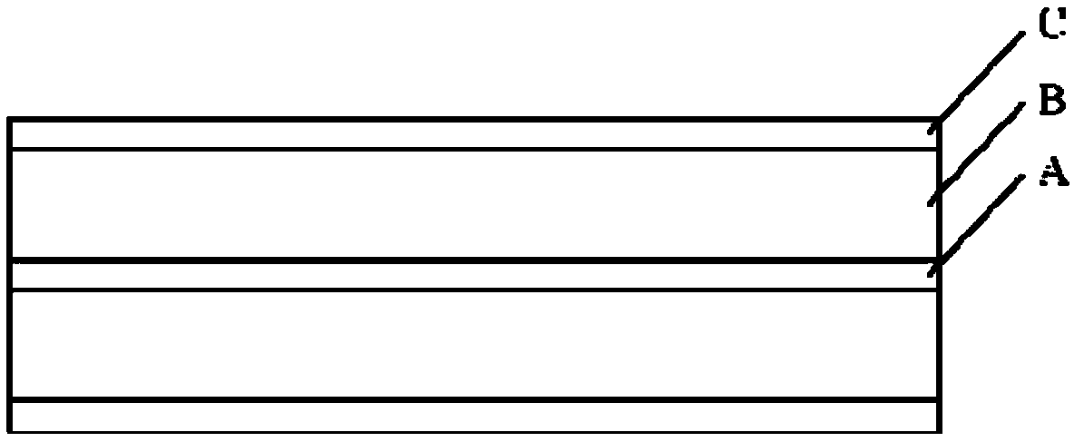
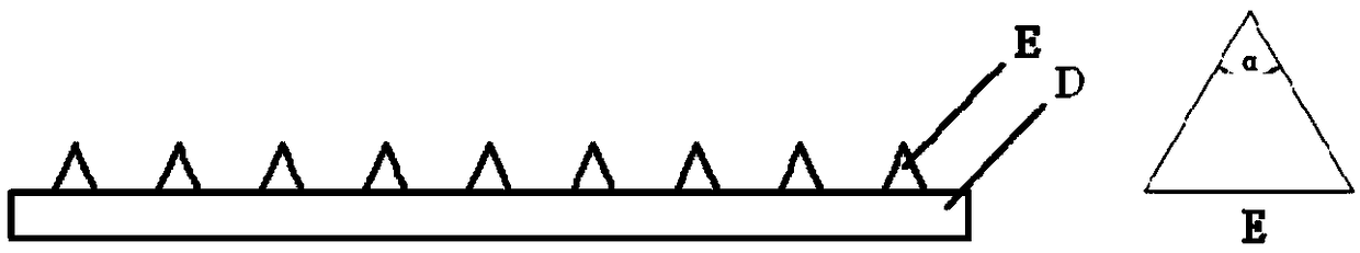
[0062] Such as Figure 1-Figure 3 As shown, the PVA solution is prepared by a needle-free free surface electrospinning method to prepare a nano-fine filter layer A, and the nano-fine filter layer A is a nano-fine filter layer with an uncharged PVA surface. When forming, the distance between the receiving plate and the solution tank is about 25cm, the voltage is about 60kV, and the rotating speed of the rotor in the solution tank that is wrapped with a wire to form a wire electrode is 70r / min. The receiving board is made of plastic, such as Figure 8 As shown, the receiving plate includes a bottom plate and a cone structure. A plurality of cone structures are evenly distributed on the bottom plate. The bottom of the cone...

Embodiment 2

[0069] Polylactic acid (M w =6.0×10 5 g / mol) after vacuum drying (60°C, 10h) for use.

[0070] Such as Figure 1-Figure 3 As shown, the PLA solution is prepared by a melt-blown electrospinning method to prepare a nano-fine filter layer A, and the nano-fine filter layer A is a nano-fine filter layer charged on the surface of PLA. During molding, the distance between the receiving plate and the melt-blown electrostatic spinneret is about 20 cm, the voltage is about 60 kV, and the PLA melt is melt-blown electrospun at a flow rate of 0.3 cc / min. The material of the receiving plate is a stainless steel belt, with a receiving surface structure such as Figure 9 As shown, the receiving surface includes a bottom plate and a cone structure. Multiple cone structures are evenly distributed on the bottom plate. The bottom of the cone structure is a square, the side length F of the square is 1.41mm, and the distribution density of the cone structures is 60. / cm 2 , the height of the t...

Embodiment 3

[0075] Polycaprolactone (M w =1.2×10 6 g / mol) after vacuum drying (50°C, 8h), using dimethylacetamide as a solvent, heating up to 60°C and stirring for 2h to obtain a uniform PCL solution with a mass concentration of 15%, and standing for defoaming for 3h.

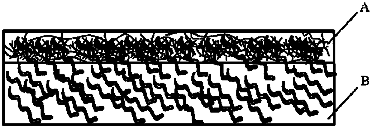
[0076] Such as Figure 1-Figure 3 As shown, the PCL solution is prepared by a double-needle electrospinning method to prepare a nano-fine filter layer A, and the nano-fine filter layer A is a charged nano-fine filter layer on the surface of PCL. When forming, the distance between the receiving plate and the needle is about 12cm, the voltage is about 15kV, and the PCL solution is electrospun at a flow rate of 0.5mL / h. The material of the receiving plate is silicon wafer, the receiving plate has a grid diameter of 0.04mm and a density of 80 pieces / cm 2 , a circular grid with a height of 0.02mm. The obtained nano fine filter layer A has a grid structure, and the PCL surface is charged, such as figure 2 As shown, there i...


PUM

PropertyMeasurementUnit
diameteraaaaaaaaaa
diameteraaaaaaaaaa
Basis weightaaaaaaaaaa

Abstract

The invention discloses an efficient low-resistance nano-fiber microscopic gradient structure filtering material and a preparation method thereof. The filtering material comprises a nanometer fine filtering layer, a micrometer support primary filtering layer and protective surface layers, wherein the micrometer support primary filtering layer and the nanometer fine filtering layer are interactively overlaid, and arranged between the two protective surface layers. The nanometer fine filtering layer has a grid structure, and the nanometer fine filtering layer is composed of a plane matrix fiberlayer and cone structures, wherein fibers between the tips of the cone structures and a grid matrix fiber layer have an oriented structure along the tips and the plane matrix fiber layer. By means ofthe filtering material without electricity, the efficiency of filtering NaCl aerosol with the mass median aerodynamic diameter of 0.26 micrometer is 99.9-99.999%, and the pressure is reduced to 130-300 Pa; by means of the filtering material which is treated by electricity, the efficiency of filtering the NaCl aerosol with the mass median aerodynamic diameter of 0.26 micrometer is 99.9-99.999%, andthe pressure is reduced to 30-250 Pa.

Description

technical field [0001] The invention relates to the field of air filtration, in particular to a gradient composite structure filter medium material with good filtering effect and a preparation process thereof. Background technique [0002] Air is a necessary condition for human survival. Due to the influence of production and various human activities, especially the large and random discharge of industrial waste gas, the air contains excessive dust and harmful gases and is polluted to varying degrees. In the past few years, PM2.5 has attracted widespread attention from the society. Dust can cause great harm to organs such as the respiratory tract and eyes. According to the "Green GDP Accounting Report", the annual loss caused by environmental pollution in Beijing alone is as high as more than 11.6 billion yuan, of which the economic loss caused by air pollution to Beijing is the most serious, as high as 9.52 billion yuan, accounting for the total loss caused by pollution. I...

Claims


Application Information

Patent Timeline
Patent Type & Authority Applications(China)
IPC IPC(8): D04H1/541D04H1/544D04H1/545D04H1/548D04H1/549D04H1/55D04H1/559D04H1/728B01D39/14
CPCB01D39/14D04H1/541D04H1/544D04H1/545D04H1/548D04H1/549D04H1/55D04H1/559D04H1/728B01D39/1623B01D39/18B01D39/2017B01D39/2065B01D39/2082B01D2239/0233B01D2239/025B01D2239/0435B01D2239/0622B01D2239/0627B01D2239/0654B01D2239/0668B01D2239/1233B01D39/163B01D2239/0618B01D2239/0631B01D2239/10B01D2239/1291D10B2505/04
Inventor 严玉蓉张鹏朱锐钿赵耀明邓玲利邹飞杨苏邯张文韬
Owner SOUTH CHINA UNIV OF TECH
Why Eureka
Try Eureka