Composite deposition method combined magnetic field arc ion plating and high-power pulse magnetron sputtering

A magnetron sputtering compound and high-power pulse technology, which is applied in the field of material surface treatment, can solve the problems of deposition position limitation and workpiece shape limitation, large particle defects, low arc plasma transmission efficiency, etc., and achieve compensation for discharge instability, The effect of improving utilization efficiency and ensuring uniformity

Pending Publication Date: 2019-07-09
魏永强
View PDF4 Cites 1 Cited by
  • Summary
  • Abstract
  • Description
  • Claims
  • Application Information

AI Technical Summary

Problems solved by technology

[0006] The purpose of the present invention is to solve the problem of low ionization rate and thin film deposition efficiency of traditional magnetron sputtering technology, the limitation of high melting point target material use, and the current high-power pulse magnetron sputtering. The plating method uses high melting point targets, low melting point pure metals (such as aluminum, tin) or multi-element alloy materials (such as AlSi alloys) and non-metallic materials (such as graphite and semiconductor materials Si) as targets that are prone to large particle defects, bending Low-efficiency arc plasma transmission caused by low-type magnetic filtering technology, restrictions on the use of target elements and uniform ablation, thin film deposition density and defects, deposition position restrictions and workpiece shape restrictions caused by vacuum chamber space and target source layout design, etc. Use pure metals with low melting points (such as aluminum, tin) or multi-element alloy materials (such as AlSi alloys) and non-metallic materials (such as graphite and semiconductor materials Si, etc.) as targets for high-power pulsed magnetron sputtering, and then use arc ions The plating method realizes the high melting point refractory target material to produce continuous, stable and high ionization rate plasma, combined with the combined effect of the magnetic field constraint of the movable coil device and the self-bias electric field attraction to eliminate the large particle defects contained in the arc plasma At the same time, the moving coil device is used to control the transmission direction of the composite plasma of high-power pulse magnetron sputtering and arc ion plating in the vacuum chamber, so as to realize the control and adjustment of the film deposition and film composition on the surface of the substrate workpiece at any position in the vacuum chamber, reducing The loss of compound plasma in the vacuum chamber overcomes the problem of uneven film deposition caused by the limitation of the position of the vacuum chamber and the target source or the limitation of the shape of the substrate, so that the surface of the workpiece can adjust the ion energy under the condition of applying a negative bias voltage. Piezoelectric field inhibition removes large particle defects in arc plasma, prepares continuous and dense high-quality films, and at the same time realizes the control of the content of target elements in the film, reduces the production cost of using alloy targets, and improves the transmission efficiency of plasma. To increase the deposition rate of the film and reduce or even eliminate the adverse effects of large particle defects on the microstructure, continuous dense deposition and performance of the film, a composite deposition method of arc ion plating and high-power pulse magnetron sputtering combined with a magnetic field is proposed

Method used


Image

  • Composite deposition method combined magnetic field arc ion plating and high-power pulse magnetron sputtering
  • Composite deposition method combined magnetic field arc ion plating and high-power pulse magnetron sputtering
  • Composite deposition method combined magnetic field arc ion plating and high-power pulse magnetron sputtering

Examples


specific Embodiment approach 1

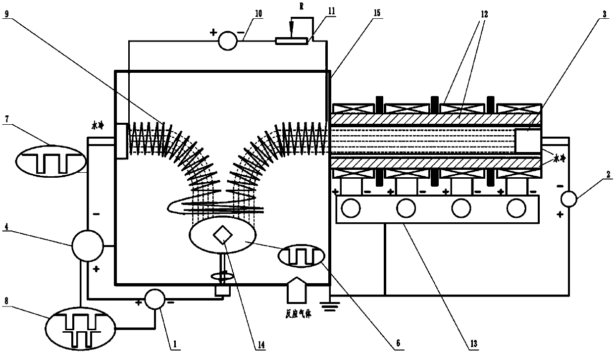
[0022] Specific implementation mode 1: the following combination figure 1 , 2 And 3 illustrate this embodiment, the combined magnetic field arc ion plating and high-power pulse magnetron sputtering composite deposition method in this embodiment uses a device including a bias power supply (1), an arc power supply (2), and an arc ion plating target source (3) ), high power pulse magnetron sputtering power supply (4), high power pulse magnetron sputtering target source (5), bias power waveform oscilloscope (6), high power pulse magnetron sputtering power supply waveform oscilloscope (7), Waveform synchronization matching device (8), movable coil device (9), movable coil device power supply (10), rheostat device (11), multi-stage magnetic field device (12), multi-stage magnetic field device power supply (13), sample stage (14) ) And the vacuum chamber (15);

[0023] In this device:

[0024] The substrate workpiece to be processed is placed on the sample table (14) in the vacuum chambe...

specific Embodiment approach 2

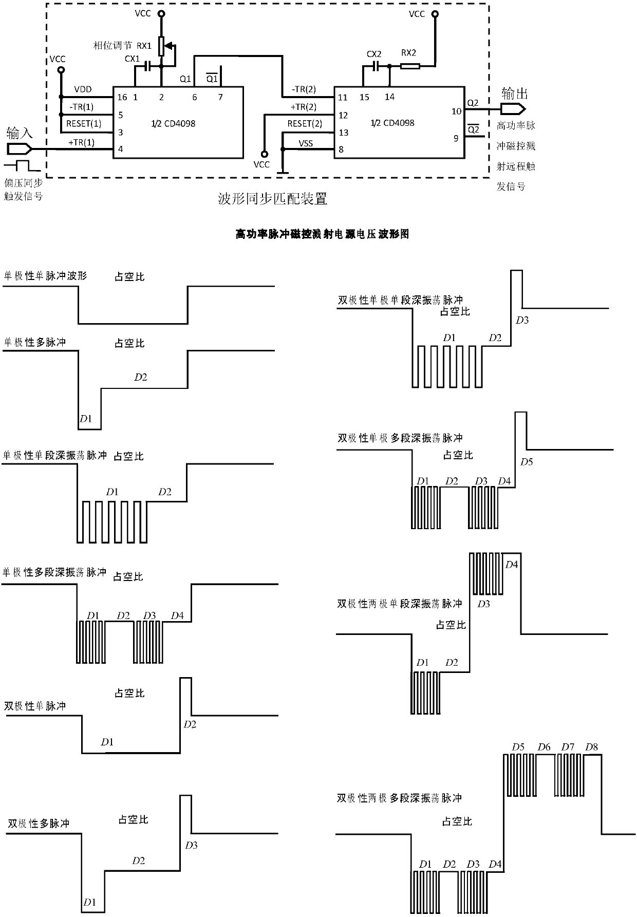
[0039] Second embodiment: The difference between this embodiment and the first embodiment is that the active magnetic field arc ion plating is connected with the high-power pulsed magnetron sputtering composite deposition method, the arc power supply (2) is turned on, and the multi-level magnetic field device power supply ( 13) Adjust the multi-level magnetic field device (12), turn on the power supply of the movable coil device (10), adjust the movable coil device (9), adjust the output resistance of the rheostat device (11), and the waveform synchronization matching device (8) controls the bias power supply ( 1) Turn on at the same time as the high-power pulsed magnetron sputtering power supply (4), the output pulse period of the high-power pulsed magnetron sputtering power supply (4) is an integer multiple of the output pulse of the bias power supply (1), such as image 3 As shown, the pulse period output by the high-power pulsed magnetron sputtering power supply (4) is 8 tim...

specific Embodiment approach 3

[0040] Specific embodiment 3: The difference between this embodiment and the first embodiment is that the active magnetic field arc ion plating is connected with the high-power pulsed magnetron sputtering composite deposition method, the arc power supply (2) is turned on, and the power supply of the multi-level magnetic field device is turned on ( 13) Adjust the multi-level magnetic field device (12), turn on the power supply of the movable coil device (10), adjust the movable coil device (9), adjust the output resistance of the rheostat device (11), and the waveform synchronization matching device (8) controls the bias power supply ( 1) Turn on simultaneously with the high-power pulsed magnetron sputtering power supply (4), the high-power pulsed magnetron sputtering power supply (4) outputs high-power pulses and the bias voltage power supply (1) the phase of the output bias pulse waveform is adjustable, such as image 3 As shown, when the pulse width is the same, the different ...


PUM

PropertyMeasurementUnit
hardnessaaaaaaaaaa

Abstract

The invention discloses a composite deposition method combined magnetic field arc ion plating and high-power pulse magnetron sputtering, and belongs to the technical field of material surface treatment. The problems such as pollution of macroparticles to thin films and the use limitation of target materials in the arc ion plating, and the losses of arc plasmas and the instability of high-power pulse magnetron sputtering discharge in the transmission process of a magnetic filter device are solved. Devices relating to the composite deposition method combined the magnetic field arc ion plating and the high-power pulse magnetron sputtering comprise a bias voltage power source, an arc ion plating target source, a power source of the arc ion plating target source, a multi-stage magnetic field device, a power source of the multi-stage magnetic field device, a movable coil device, a power source of the movable coil device, a waveform matching device, a high-power pulse magnetron sputtering target source, a power source of the high-power pulse magnetron sputtering target source, an oscilloscope and a vacuum chamber. The thin film deposition comprises the steps that the devices are connected, and a system is started; and when a vacuum degree in the vacuum chamber is less than 10<-4> Pa, a working gas is introduced, and a film plating power source is turned on. The bias voltage power source adjusts the energy of plasmas, the multi-stage magnetic field device and the movable coil device eliminate macroparticle defects and guide the transmission of composite plasmas, the losses in the vacuum chamber are reduced, and technological parameters are set.

Description

Technical field [0001] The invention relates to a composite deposition method combining magnetic field arc ion plating and high-power pulse magnetron sputtering, and belongs to the technical field of material surface treatment. Background technique [0002] In the process of preparing thin films by arc ion plating, the arc spot current density is as high as 2.5~5×10 10 A / m 2 , Causing molten liquid metal to appear at the arc spot on the surface of the target, which is sprayed out in the form of droplets under the action of the partial plasma pressure, attached to the surface of the film or embedded in the film to form "Macroparticles" (Macroparticles) Defects (BoxmanR L, Goldsmith S. Macroparticle contamination in cathodic arc coatings: generation, transport and control [J]. Surf Coat Tech, 1992, 52(1): 39-50.). In arc plasma, since the moving speed of electrons is much greater than that of ions, the number of electrons reaching the surface of large particles per unit time is gre...

Claims


Application Information

Patent Timeline
Patent Type & Authority Applications(China)
IPC IPC(8): C23C14/32C23C14/56C23C14/35
CPCC23C14/325C23C14/564C23C14/35C23C14/3485
Inventor 魏永强王好平宗晓亚张华阳侯军兴蒋志强
Owner 魏永强
Why Eureka
Try Eureka