A photoelectric integrated thin film power supply system and its preparation and application

A power system and thin-film battery technology, applied in the field of batteries, can solve the problems of reduced portability and safety, lower battery energy conversion efficiency, and no consideration of thin-film integration.

Active Publication Date: 2020-08-04
CENT SOUTH UNIV
View PDF4 Cites 0 Cited by
  • Summary
  • Abstract
  • Description
  • Claims
  • Application Information

AI Technical Summary

Problems solved by technology

[0004] Liming Dai (Nature Communications, 2015, 6, 8103) et al. designed a photoelectric integrated power system connected by wires, in which the solar cell is CH 3 NH 3 PB 3 Perovskite battery, the positive electrode material in the lithium battery is LiFePO 4 , the anode material is Li 4 Ti 5 o 12 , the battery system has good discharge performance, but the design uses wire connection, which does not consider the integration of thin films of materials, and the use is complicated. At the same time, the introduction of wires reduces the overall energy conversion efficiency of the battery
At present, there are optoelectronic integrated power supply design ideas, and the connection of two kinds of power supply (physical power supply and chemical power supply) is mostly used. Although the chemical power supply part uses lithium-ion batteries, its thin film and mechanical integration are rarely considered. Zhong LinWang ( Nano letters, 2012, 12(5): 2520-2523) et al. designed TiO 2 Although the power supply system has achieved photoelectric integration, its lithium battery is designed with an electrolyte battery, which greatly reduces its portability and safety.

Method used


Image

  • A photoelectric integrated thin film power supply system and its preparation and application
  • A photoelectric integrated thin film power supply system and its preparation and application

Examples


Embodiment 1

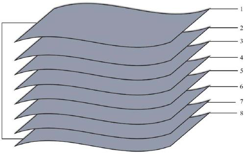
[0094] The invention provides a photoelectric integrated thin film power supply system, its structure includes a lithium ion battery part and a solar battery part, the specific structure is as follows figure 1 As shown, 5-Mo foil is used as the film substrate, 4-CZTS is sputtered on one side by magnetron sputtering, 6-CZTS is sputtered on the other side of the 5-Mo foil by magnetron sputtering, annealed Afterwards, continue to use the film as the substrate, continue to sputter the electrolyte 3-LiPON on the 4-CZTS side, and the positive electrode material 2-LiCoO 2 , the current collector 1-Al is used as the part of the lithium-ion battery, the buffer layer 7-CdS is sputtered on the 6-CZTS side, and the window layer 8-IZO / ITO is used as the solar cell part, where the 8-window layer is connected to the 1-current collector , this type of connection will not connect other layers. The battery system is packaged with silicone resin adhesive, and the two stages of 1-Al and 5-Mo foi...

Embodiment 2

[0097] The invention provides an optoelectronic integrated film power system, the structure of which includes a lithium ion battery part and a solar battery part, wherein 5-Mo foil is used as a film substrate, and 4-CZTS is respectively sputtered by magnetron sputtering on one side, and The other side of the 5-Mo foil was sputtered with 6-CZTS by magnetron sputtering. After annealing, the film continued to be used as the substrate, and the electrolyte 3-LiPON was sputtered on the 4-CZTS side, and the positive electrode material 2-LiNi 0.8 mn 0.1 co 0.1 o 2 , the current collector 1-Al is used as the part of the lithium-ion battery, the buffer layer 7-CdS is sputtered on the 6-CZTS side, and the window layer 8-IZO / ITO is used as the solar cell part, where the 8-window layer is connected to the 1-current collector , this type of connection will not connect other layers. The battery system is packaged with silicone resin adhesive, and the two stages of 1-Al and 5-Mo foil are u...

Embodiment 3

[0100] The invention provides an optoelectronic integrated thin-film power supply system, the structure of which includes a lithium ion battery part and a solar battery part, wherein 6-Mo foil is used as a thin film substrate, and magnetron sputtering is used to sputter 5-Cu, 4 -CZTS sputtered 7-CZTS on the other side of the 6-Mo foil by magnetron sputtering. After annealing, the film continued to be used as the substrate, and the electrolyte 3-LiPON was continued to be sputtered on the 4-CZTS side, and the positive electrode material 2- LiNi 0.5 mn 0.3 co 0.2 o 2 , the current collector 1-Al is used as the part of the lithium-ion battery, the buffer layer 7-CdS is sputtered on the 6-CZTS side, and the window layer 8-IZO / ITO is used as the solar cell part, where the 8-window layer is connected to the 1-current collector , this type of connection will not connect other layers. The battery system is packaged with silicone resin adhesive, and the two stages of 1-Al and 5-Mo f...


PUM

PropertyMeasurementUnit
thicknessaaaaaaaaaa
thicknessaaaaaaaaaa
thicknessaaaaaaaaaa

Abstract

The invention discloses a photoelectric integrated power supply and a preparation method thereof. A magnetron sputtering method is adopted to prepare a photoelectric integrated thin film power supplysystem. The power supply comprises a thin film substrate, a lithium-ion thin film battery arranged on one surface of the thin film substrate in a composite mode and a solar battery arranged on the other surface of the thin film substrate in a composite mode; and a cathode material layer and a light absorption layer are made of a silicon-based material or at least one of sulfide, oxide and selenium-based matter of at least one of copper, zinc, titanium, iron and tin. Through the design method, the defects of large scale, low efficiency and the like, caused by the situation that traditionally anexternal circuit is used to connect a solar battery and a lithium-ion battery, are overcome, and the energy efficiency and portability of the power supply system can be greatly improved. Meanwhile, by use of an electrode material, integrated application of the material is realized; and through the application mode, in the heat treatment process of a thin film made of the same substance, high crystallinity of the substance under the same temperature can be guaranteed, electrochemical properties of the material are improved, and battery conversion efficiency is improved.

Description

technical field [0001] The invention belongs to the field of batteries, and in particular relates to a photoelectric integrated film power supply system. Background technique [0002] Energy is an important material basis for developing the national economy and improving people's living standards, and it is also an important factor that directly affects economic development. Since the beginning of the 21st century, problems such as resource shortage, environmental pollution, and greenhouse effect caused by traditional energy utilization methods have become increasingly prominent. Improving the energy structure and developing efficient and clean new energy sources has become a global consensus. At present, solar energy radiates up to 125,000TW of energy to the earth every year, and 40 seconds of radiation on the ground is equivalent to the energy of 21 billion barrels of oil sent to the earth, which is equivalent to the sum of energy consumed by human beings in a day. In add...

Claims


Application Information

Patent Timeline
Patent Type & Authority Patents(China)
IPC IPC(8): H01M10/0525H02S40/38
CPCH01M10/0525H02S40/38Y02E10/50Y02E60/10Y02E70/30
Inventor 赖延清刘芳洋王麒羽汪齐张治安洪波张凯李劼
Owner CENT SOUTH UNIV
Why Eureka
Try Eureka