Structure of silicon-based metal intermediate layer compound semiconductor wafer and preparation method thereof
A compound and semiconductor technology, applied in semiconductor/solid-state device manufacturing, semiconductor devices, semiconductor/solid-state device components, etc. Reliability and stability of devices and other issues to achieve the effect of reducing thermal stress, improving manufacturing process, and expanding application fields
- Summary
- Abstract
- Description
- Claims
- Application Information
AI Technical Summary
Problems solved by technology
Method used
Image
Examples
preparation example Construction
[0049] The invention provides a structure and preparation method of a silicon-based metal interlayer compound semiconductor wafer, which belongs to the field of semiconductor technology, and the structure comprises from top to bottom: a compound semiconductor wafer, a metal layer M 1 , metal layer M 2 and a silicon chip; the preparation method of the structure includes: using electron beam evaporation technology to vapor-deposit a metal layer on the compound semiconductor wafer and the silicon chip. Then use ion implantation and wafer bonding technology to realize silicon-based compound semiconductor wafer thin film. The introduction of the metal layer of the present invention can effectively alleviate the stress introduced by the difference in thermal expansion coefficient between the compound semiconductor wafer and the silicon chip; the present invention improves and improves the manufacturing process of semiconductor devices, and expands the application of wafer bonding te...
Embodiment 1
[0077] The invention provides a structure and a preparation method of a silicon-based metal alloy interlayer compound semiconductor wafer, comprising:
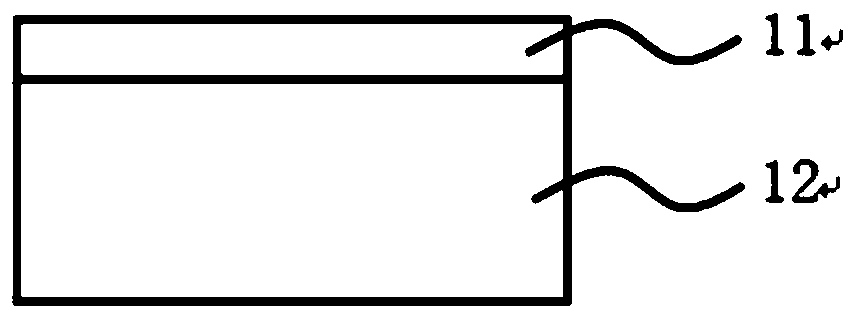
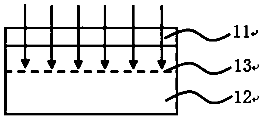
[0078] Step 1: Processing of the GaAs wafer, such as Figure 1-5 shown.
[0079] 1a. Select a gallium arsenide wafer 12, and perform PECVD on the upper surface of the gallium arsenide wafer 12. The deposited material is a silicon dioxide sacrificial layer 11, and the thickness of the silicon dioxide sacrificial layer 11 is 100 nm; figure 1 shown;
[0080] 1b. After the silicon dioxide sacrificial layer 11 is deposited, the gallium arsenide wafer 12 is implanted with ions through the silicon dioxide sacrificial layer 11, the implanted material is hydrogen ions, and the implanted dose is 1×10¹⁷ h + / cm 2 , the injected energy is 100keV; if figure 2 shown;
[0081] 1c. After the implantation is completed, the silicon dioxide sacrificial layer 11 on the gallium arsenide wafer 12 is completely removed by a CMP process, and th...
Embodiment 2
[0097] The invention provides a structure and a preparation method of a silicon-based metal alloy interlayer compound semiconductor wafer, comprising:
[0098] Step 1: Processing of the GaN wafer, such as Figures 9 to 13 shown.
[0099] 1a. Select a gallium nitride wafer 32, and perform PECVD on the upper surface of the gallium nitride wafer 32. The deposited material is a silicon nitride sacrificial layer 14, and the thickness of the silicon nitride sacrificial layer 14 is 200nm, such as Figure 8 shown;
[0100] 1b. After the silicon nitride sacrificial layer 14 is deposited, ion implantation is performed on the gallium nitride wafer 32 through the silicon nitride sacrificial layer 14. The implanted material is a mixture of hydrogen ions and helium ions, and the implantation dose of hydrogen ions is 2× 10 16 h + / cm 2 , the implantation energy is 120keV, and the implantation dose of helium ions is 7.5×10 15 he + / cm 2 , the injected energy is 150keV, such as Figur...
PUM
| Property | Measurement | Unit |
|---|---|---|
| thickness | aaaaa | aaaaa |
| thickness | aaaaa | aaaaa |
| thickness | aaaaa | aaaaa |
Abstract
Description
Claims
Application Information
 - R&D
- Intellectual Property
- Life Sciences
- Materials
- Tech Scout
- Unparalleled Data Quality
- Higher Quality Content
- 60% Fewer Hallucinations
Browse by: Latest US Patents, China's latest patents, Technical Efficacy Thesaurus, Application Domain, Technology Topic, Popular Technical Reports.
© 2025 PatSnap. All rights reserved.Legal|Privacy policy|Modern Slavery Act Transparency Statement|Sitemap|About US| Contact US: help@patsnap.com


