Electric arc-laser composite additive manufacturing method

A technology of additive manufacturing and electric arc, which is applied in the field of additive manufacturing, can solve the problems of large internal stress, no improvement in the stress distribution of the forming structure, and coarse grains, so as to reduce anisotropy, improve dimensional accuracy and structural performance, and reduce The effect of martensitic structure

Inactive Publication Date: 2020-03-06
725TH RES INST OF CHINA SHIPBUILDING INDAL CORP
View PDF9 Cites 11 Cited by
  • Summary
  • Abstract
  • Description
  • Claims
  • Application Information

AI Technical Summary

Problems solved by technology

[0003] At present, the existing composite additive manufacturing method is mainly the composite of heat source, such as the composite heat source of electric arc and laser as the heat source of wire melting, which is piled up layer by layer. Although the efficiency has been improved, the grains are still coarse. , large internal stress and other deficiencies; the additive method of surface cleaning and arc additive composite man

Method used


Image

  • Electric arc-laser composite additive manufacturing method
  • Electric arc-laser composite additive manufacturing method
  • Electric arc-laser composite additive manufacturing method

Examples


Embodiment 1

[0025] An electric arc-laser composite additive manufacturing method, comprising the following steps:

[0026] (1) Cleaning: Mechanically polish the surface of the metal parts to be processed, use acetone and alcohol solvents to ultrasonically clean them to remove oil stains, dry them for use, and then measure the size of the cleaned metal parts to be processed and place them on the workbench. Fix it with a clamp and set it aside;

[0027] (2) Arc additive manufacturing: establish a 3D model of the metal parts to be processed, obtain the 3D model file, slice the file, obtain the processing path of arc additive, and set the process parameters of arc additive, in an inert gas Under the environment, the parts to be processed are deposited layer by layer by arc fuse;

[0028] (3) Laser heat treatment: According to the material of the processed metal parts and the effective wall thickness of the layer to be printed, through the simulation of the temperature field, the correspondin...

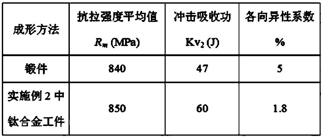
Embodiment 2

[0036] As another embodiment of the present invention:

[0037] The metal part to be processed is a titanium alloy, such as a Ti80 titanium alloy substrate, and the specification is According to the mass fraction, the Ti80 titanium alloy substrate includes the following chemical components: 5.5-6.5% Al, 2.5-3.5% Nb, 1.5-2.5% Zr, 0.6-1.5% Mo, 0.25% Fe, 0.15% Si, 0.10% of C, 0.05% of N, 0.015% of H, 0.15% of O, and the balance is Ti.

[0038] Mechanically polish the surface of the Ti80 titanium alloy substrate, use acetone and alcohol solvents to ultrasonically clean it to remove oil stains, dry it for use, then measure the size of the cleaned metal parts to be processed, place them on the workbench, fix them with fixtures, and set aside ;

[0039]Establish a 3D model of the metal part to be processed, obtain the 3D model file, slice the file, obtain the processing path of the arc additive material, and set the process parameters of the arc additive material, and adopt the ar...


PUM


Abstract

The invention discloses an electric arc-laser composite additive manufacturing method. The method comprises the following steps that the surface of a metal part to be machined is subjected to mechanical polishing, cleaning for oil stain removing and drying, the size of the metal part is measured, and then the metal part is placed on a workbench and fixed with a clamp for standby use; a three-dimensional model of the metal part to be machined is established to obtain a three-dimensional model file, the file is subjected to slicing treatment, a machining path of the electric arc additive material is obtained, process parameters of the electric arc additive material are set, and the part to be machined is subjected to layered sedimentation under an inert gas environment by adopting an electric arc fuse wire; and according to the texture of the machined metal part and the effective wall thickness of a to-be-printed layer, a corresponding laser scanning track, scanning power and scanning speed are selected through simulation of a temperature field, and the printed cladding layer is subjected to laser heat treatment. According to the method, the coarse columnar crystals in the forming part can be improved, the martensitic structure and dislocation are reduced, the anisotropy of additive manufacturing is remarkably reduced, and the forming precision is effectively controlled.

Description

technical field [0001] The invention relates to the field of additive manufacturing, in particular to an arc-laser composite additive manufacturing method. Background technique [0002] The additive manufacturing technology of metal parts was developed on the basis of rapid prototype manufacturing technology in the late 1990s, and it is an advanced manufacturing technology for directly preparing fully dense metal parts. It combines rapid prototyping technology, high-power heat source fusion deposition technology and advanced material preparation technology, adopts the idea of ​​digital discrete / build-up forming additive manufacturing, melts and deposits synchronously transported metal powder or wire through high-power heat source, and deposits on the substrate The upper layer is piled up layer by layer, so as to realize the "near net shape manufacturing" of high-performance fully dense metal parts with complex shape, fine structure and uniform composition. The metal materia...

Claims


Application Information

Patent Timeline
IPC IPC(8): B23K26/348B23K26/342
CPCB23K26/342B23K26/348
Inventor 张帅锋卢晓阳蒋鹏于冰冰
Owner 725TH RES INST OF CHINA SHIPBUILDING INDAL CORP
Why Eureka
Try Eureka