Method of producing jet fuel
A jet fuel and material technology, applied in the hydrogenation field of jet fuel production, can solve problems such as poor product stability, high nitrogen content, harsh operating conditions, etc.
- Summary
- Abstract
- Description
- Claims
- Application Information
AI Technical Summary
Problems solved by technology
Method used
Image

Examples
preparation example
[0053] Take by weighing 2000 grams of aluminum hydroxide powder (dried rubber powder produced by Changling Branch Catalyst Factory, dry basis 72% by weight), extrude into a butterfly bar with a circumscribed circle diameter of 1.3 mm with an extruder, and wet the bar at 120 ° C Drying for 4 hours and calcining at 600° C. for 3 hours to obtain carrier Z1. The radial crushing strength of the Z1 carrier is 29.5N / mm, the water absorption rate is 0.85ml / g, the pore volume is 0.67ml / g, and the specific surface area is 275m 2 / g.
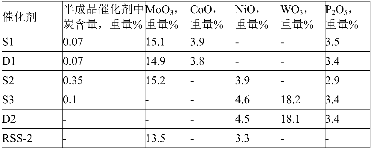
[0054] The hydrorefining catalyst S1 used in the embodiment is prepared by the following method:
[0055] Weigh 40 grams of molybdenum trioxide, 19 grams of basic cobalt carbonate, 15 grams of phosphoric acid, and 20 grams of citric acid into 140 grams of deionized water, heat and stir to dissolve to obtain a clear impregnation solution, and the measured pH is 3.5. Using the saturated impregnation method to impregnate 200 grams of alumina carrier Z1 with...
Embodiment 1
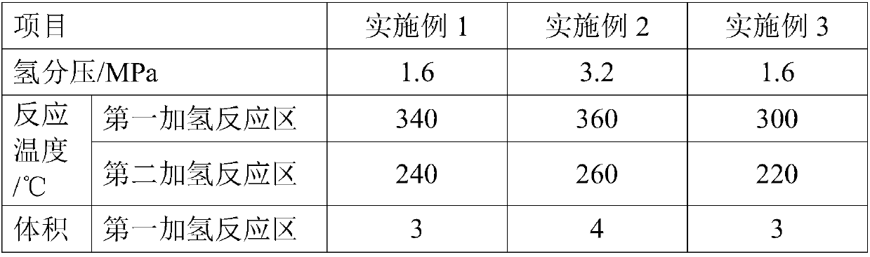
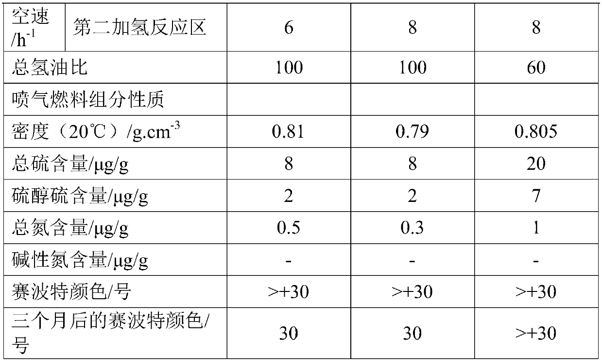
[0071] A high-nitrogen kerosene fraction is used as raw material oil A. After the raw material oil A is boosted and mixed with hydrogen-containing stream, it enters the hydrogenation reactor, passes through the first hydrogenation reaction zone and the second hydrogenation reaction zone in turn, and is combined with hydrofining Catalyst S1 is contacted for reaction, the hydrogen partial pressure at the reactor inlet is 1.6MPa, the reaction temperature in the first hydrogenation reaction zone is 340°C, the reaction temperature in the second hydrogenation reaction zone is 240°C, and the liquid-hour volume of the first hydrogenation reaction zone Airspeed is 3.0h -1 , the liquid hourly volumetric space velocity of the second hydrogenation reaction zone is 6.0h -1 , the volume ratio of hydrogen to oil in the first hydrogenation reaction zone and the second hydrogenation reaction zone is 100.
[0072] The effluent of the hydrogenation reactor undergoes gas-liquid separation in the...
Embodiment 2
[0074] A high-sulfur and high-nitrogen kerosene distillate is used as raw material oil B. After the raw material oil B is boosted and mixed with hydrogen-containing stream, it enters the hydrogenation reactor, and passes through the first hydrogenation reaction zone and the second hydrogenation reaction zone in turn. The hydrogen refining catalyst S2 is contacted for reaction, the hydrogen partial pressure at the reactor inlet is 3.2MPa, the reaction temperature in the first hydrogenation reaction zone is 360°C, the reaction temperature in the second hydrogenation reaction zone is 260°C, the liquid in the first hydrogenation reaction zone The hourly volume space velocity is 4.0h -1 , the liquid hourly volume space velocity of the second hydrogenation reaction zone is 8.0h -1 , the volume ratio of hydrogen to oil in the first hydrogenation reaction zone and the second hydrogenation reaction zone is 100.
[0075] The process of gas-liquid separation and fractionation of liquid ...
PUM
| Property | Measurement | Unit |
|---|---|---|
| Radial crushing strength | aaaaa | aaaaa |
| Pore volume | aaaaa | aaaaa |
| Specific surface area | aaaaa | aaaaa |
Abstract
Description
Claims
Application Information