
Practical carbon dioxide reduction film electrolyzer and preparation method thereof

A carbon dioxide, electrolyzer technology, applied in the direction of electrolysis components, electrolysis process, electrode shape/type, etc., can solve the problems of large internal resistance, low energy conversion rate, blockage of gas channels, etc., to achieve high practicability, broad application prospects, The effect of device area expansion

Active Publication Date: 2020-05-01
WUHAN UNIV
View PDF6 Cites 6 Cited by
  • Summary
  • Abstract
  • Description
  • Claims
  • Application Information

AI Technical Summary

Problems solved by technology

A thin-layer liquid flow electrolyzer designed with a neutral or alkaline medium combined with a gas diffusion electrode can achieve a current density of 100 milliamperes and reach a practical level, but there are other problems: neutral medium (Haas, T.et. al.Nat.Catal.2018,1,32-39.) works stably but has large internal resistance and low energy conversion rate; while alkaline medium (Verma,S.et al.ACS Energy Lett.2018,3,193-198. ) has high efficiency, but the reaction interface is easy to salt out and block the gas channels, and the consumed lye has to be replenished regularly, so it cannot work stably for a long time
[0004] In another type of tightly packed solid polymer electrolyte (SPE) membrane electrolyzer, the electrolyte layer is replaced by a thinner SPE membrane, but common acidic SPE membranes, such as DuPont's Nafion, are accompanied by severe hydrogen evolution side reactions that are difficult to However, the research on the corresponding alkaline SPE membrane has just started, and it cannot be applied alone without liquid electrolyte, and its performance cannot be compared with the similar results of thin-layer liquid flow electrolyzer.

Method used


Image

  • Practical carbon dioxide reduction film electrolyzer and preparation method thereof
  • Practical carbon dioxide reduction film electrolyzer and preparation method thereof
  • Practical carbon dioxide reduction film electrolyzer and preparation method thereof

Examples


Embodiment 1

[0032] Weigh 28mg of carbon powder (Cabot Vulcan XC-72) into a 200mL three-neck flask, add 60mL of glycerin, continue to sonicate and stir until the carbon powder is evenly dispersed in glycerin, and slowly add 2ml of chloroauric acid dropwise at 50°C under stirring and reflux conditions aqueous solution (containing 0.1mmol chloroauric acid) and 2mL sodium borohydride aqueous solution (containing 2mmol NaBH 4 ), the reaction was continued for half an hour after adding, and the product was freeze-dried to obtain a powder Au / C catalyst after repeated washing with a mixed solvent of water+ethanol and centrifugation, with a gold loading of about 40% and a particle size of about 10nm.

[0033]Cut the QAPPT film into a size of 4cm*4cm for later use, and dissolve the QAPPT film material in a mixed solvent of isopropanol / DMF (volume ratio: 1:2) to obtain a light yellow initial film solution (QAPPT content 20mg / mL), Dilute to 1 mg / mL in n-propanol system as the diluted film solution, a...

Embodiment 2

[0036] Cut the QAPPT film into a size of 4cm*4cm for later use. In addition, the film material was dissolved in a mixed solvent of isopropanol / DMF (volume ratio: 1:2) to obtain a light yellow initial film solution (QAPPT content 20mg / mL). Diluted to 1mg / mL in n-propanol system as the diluted film solution, respectively weighed carbon powder (Cabot Vulcan XC-72) and cobalt phthalocyanine (CoPc) catalyst according to the mass ratio of 4:1 and mixed them initially, with a total mass of 4mg / mL ratio into the diluted film solution, fully dispersed in an ultrasonic cleaner to form a uniform ink. Use an airbrush to evenly spray the ink to the middle area (about 18mm*18mm) of the SPE film fixed on a 70°C hot plate, and weigh the IrO 2 Prepare and disperse the ink in the same proportion, spray it on the other side of the SPE film under the same conditions, and the position is consistent with that of CoPc / C to complete the electrode preparation. Soak the membrane with the catalytic la...

Embodiment 3

[0039] Cut the QAPS membrane into a size of 4cm*4cm for later use, and dissolve the membrane material in DMF to obtain a light yellow initial membrane solution (QAPS content 20mg / mL), which is diluted to 1mg / mL in n-propanol system as a diluted membrane solution According to the mass ratio of 4:1, respectively weigh the carbon powder (Cabot Vulcan XC-72) and the cobalt phthalocyanine (CoPc) catalyst and mix them initially, add the diluted membrane solution at a ratio of 4 mg / mL to the total mass, and put them in an ultrasonic cleaner Fully dispersed to form a uniform ink. Use an airbrush to evenly spray the ink to the middle area (about 18mm*18mm) of the SPE film fixed on a 70°C hot plate, and weigh the Pt-Ru / C catalyst (60%) to prepare and disperse the ink in the same proportion. Spray coating to the other side of the SPE film under the same conditions, the position is consistent with that of CoPc / C, and the electrode preparation is completed. Soak the membrane with the cata...


PUM

PropertyMeasurementUnit
Particle sizeaaaaaaaaaa

Abstract

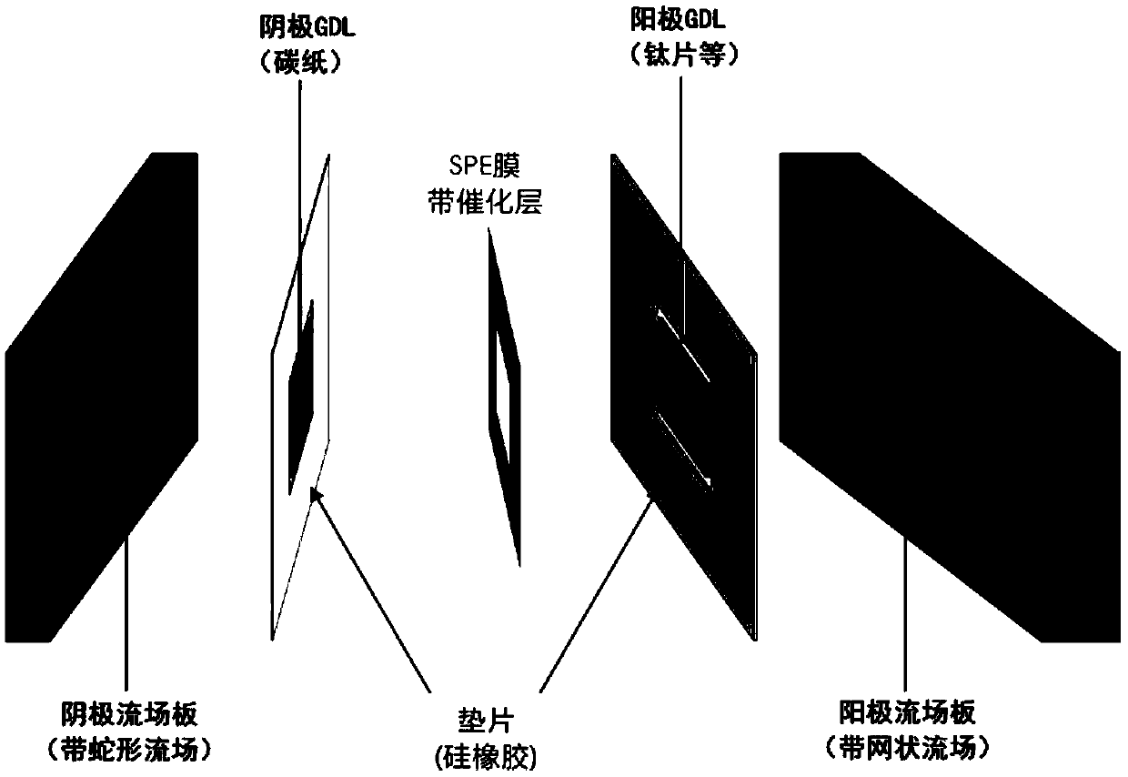
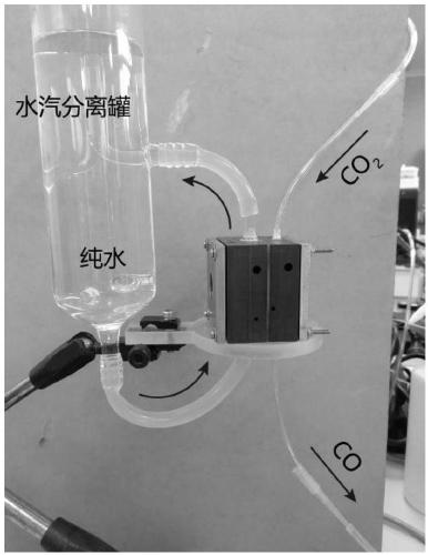
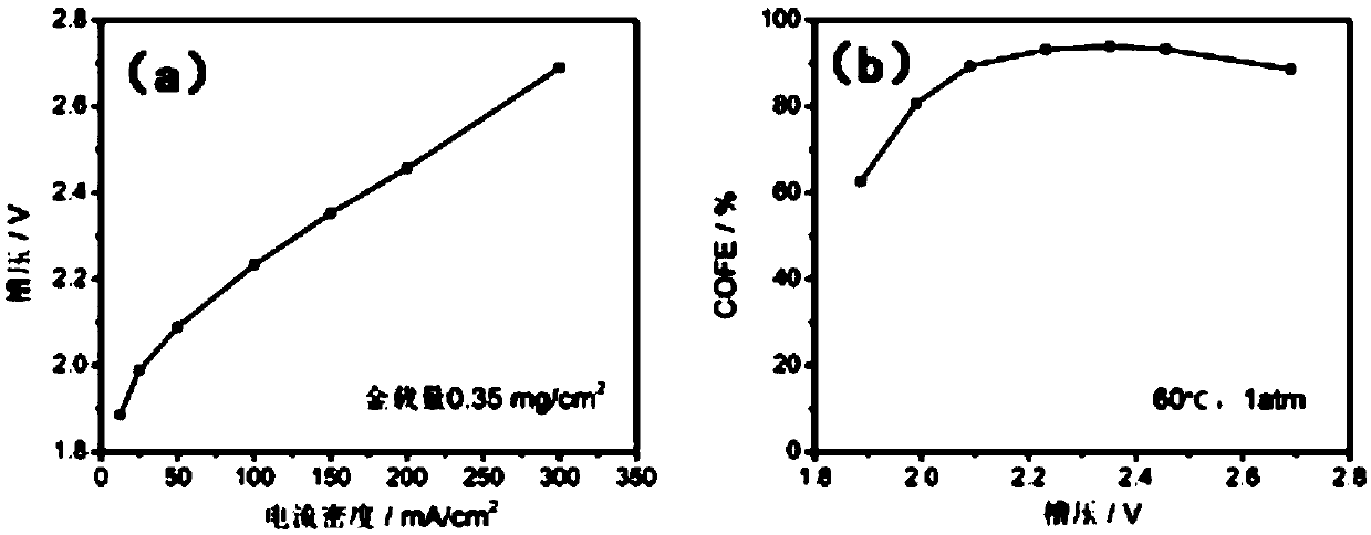
The invention discloses a practical carbon dioxide reduction film electrolyzer and a preparation method thereof, and belongs to the field of electrocatalytic carbon dioxide reduction. The film electrolyzer comprises a cathode flow field plate, a cathode gasket, a cathode diffusion layer, a membrane electrode, an anode diffusion layer, an anode gasket and an anode flow field plate which are assembled in sequence, wherein the membrane electrode comprises an SPE membrane, a cathode catalyst and an anode catalyst, the cathode catalyst and the anode catalyst are located on the two sides of the SPEmembrane respectively, the cathode flow field plate is smooth in a snake shape, and the anode flow field plate is a net-shaped flow field. The method is simple and safe to operate, the electrolyzer works efficiently and stably, the performance of the electrolyzer reaches a high level in the same field, for example, hundreds of milliamperes of current density can be achieved through a low cell voltage, the selectivity exceeds 90%, and the like, and the electrolyzer has novelty, practicability and wide prospects.

Description

technical field [0001] The invention belongs to the field of electrocatalytic carbon dioxide reduction, and relates to a practical tightly assembled carbon dioxide reduction membrane electrolysis device and a preparation method thereof. Background technique [0002] In recent years, the use of a large number of fossil fuels has led to an increase in the concentration of carbon dioxide in the atmosphere year by year, which has caused serious environmental problems such as the greenhouse effect. In addition, fossil fuels themselves are non-renewable energy and face the risk of resource depletion. Therefore, the field of low-carbon green energy and carbon dioxide conversion more and more people pay attention to. Among many conversion technologies, it is potentially feasible to use renewable energy such as solar / wind energy to generate clean electricity, and then use it to efficiently catalyze the reduction of carbon dioxide. However, most of the research is only carried out in ...

Claims


Application Information

Patent Timeline
IPC IPC(8): C25B1/00C25B9/10C25B11/02C25B9/23
CPCC25B1/00C25B11/02C25B9/23
Inventor 庄林尹征磊彭汉青周欢魏星
Owner WUHAN UNIV
Learn More