Method for 3D printing of monolithic catalyst

A monolithic catalyst and 3D printing technology, which is applied in chemical instruments and methods, catalyst activation/preparation, physical/chemical process catalysts, etc., can solve problems such as high cost, inability to realize catalyst integrated molding, complex process, etc., and achieve low cost , Improve the effect of catalytic reaction, the effect of simple process

Active Publication Date: 2020-12-11
陕西斐帛思凯科技发展有限公司
View PDF7 Cites 9 Cited by
  • Summary
  • Abstract
  • Description
  • Claims
  • Application Information

AI Technical Summary

Problems solved by technology

[0003] 3D printing technology can be closely combined with computer simulation and structural design to accurately manufacture catalysts with complex structures and optimized performance that require multiple materials to be integrally formed. Using 3D printing technology can avoid the complicated manufacturing process required by traditional preparation methods and reduce The cost of catalyst manufacturing, the traditional process is difficult to achieve the requirement of printing different parts of the same part with different materials
[0004] At present, there are some precedents of 3D printing monolithic catalysts. The Chinese patent (application number 202010167140.3, name: a 3D printing monolithic composite structure catalyst and its preparation method and application) uses laser cladding technology to process the catalyst carrier and active components. The sintering of powder is only suitable for the preparation of metal-based catalysts, and the carrier needs to be dissolved by alkaline solution in the follow-up, so the process is complicated; Chinese patent (application number 201911261246.3, name: a preparation method of a biomimetic structure monolithic catalyst based on 3D printing technology) Focus on the preparation of biomimetic structures and reduce the pressure drop of catalysts, and it is impossible to realize the integral molding of catalysts with different materials in different parts; Chinese patent (application number 201811166564.7, name: a method for preparing monolithic molecular sieve blocks by 3D printing technology) focuses on Due to the preparation of molecular sieve blocks, it is impossible to realize the integral molding of catalysts with different materials in different parts, and the cost is high

Method used


Image

  • Method for 3D printing of monolithic catalyst
  • Method for 3D printing of monolithic catalyst

Examples


Embodiment 1

[0033] Embodiment 1, a kind of method of 3D printing monolithic catalyst, comprises the following steps:

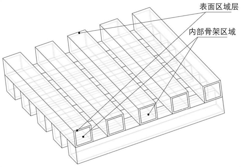
[0034] 1) Design the 3D model of the monolithic catalyst, and simulate the 3D model with different wall thickness and porosity in the COMSOL software for the catalytic experiment of methane dry reforming, and obtain the 3D model structure under the optimal mass transfer, heat transfer and conversion efficiency ,like figure 2 shown;

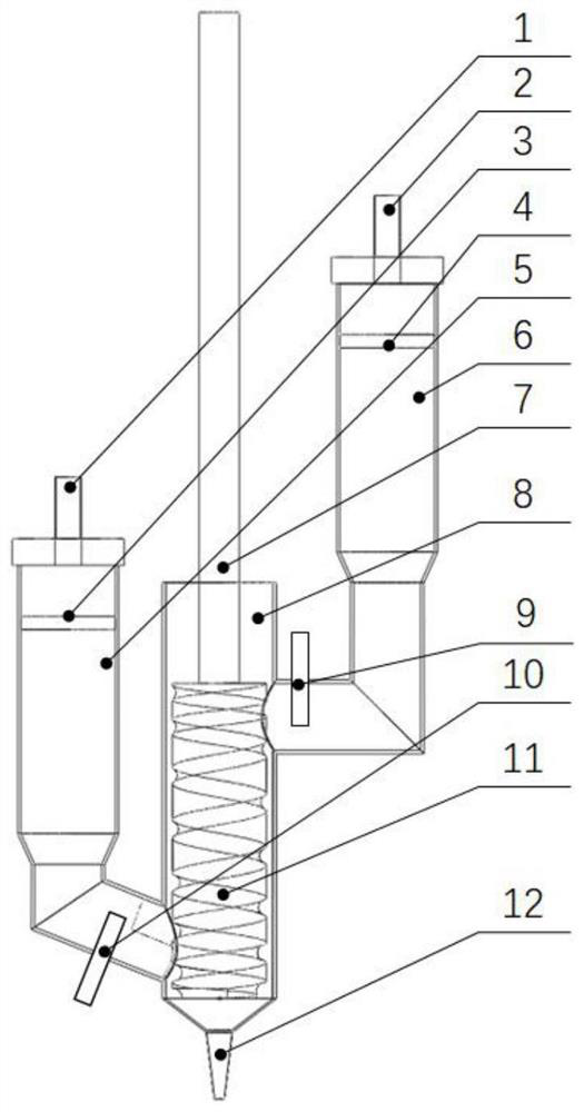
[0035] 2) Take 5.27g nickel nitrate hexahydrate, 1.03g ammonium dihydrogen phosphate, 0.1g turnip powder, 2.4g methylcellulose, 5g distilled water, and mechanically stir at a speed of 100r / min for 30min to obtain the catalytically active component slurry , into the first barrel 5; get 20g pseudo-boehmite, 2.4g10% dilute acetic acid, 18g distilled water, 0.075g scallop powder, mechanically stir at a speed of 100r / min for 30min to obtain alumina ceramic slurry, load into the second barrel 6;

[0036]Print on a printing base plate covered wi...

Embodiment 2

[0039] Example 2, the difference between Example 2 and Example 1 is that in step 4), the monolithic catalyst blank after constant temperature and humidity drying was kept at 400 ° C for 3 hours, and then cooled to room temperature with the furnace to prepare the monolithic catalyst 2.

Embodiment 3

[0047] Embodiment 3, a kind of method of 3D printing monolithic catalyst, comprises the following steps:

[0048] 1) Design the three-dimensional model of the monolithic catalyst, and simulate the catalytic experiment of the one-step preparation of ethylene glycol by using COMSOL software for the models with different wall thicknesses and porosities, and obtain the optimal mass transfer, heat transfer and conversion efficiency. 3D model structure;

[0049] 2) Take 5 g of titanium-silicon molecular sieve TS-1, 0.18 g of scallop powder, 2 g of silica sol, and 4 g of distilled water, mechanically stir at a speed of 100 r / min for 30 min to obtain a slurry of catalytically active components, and load it into the first cylinder 5; Take 20g of silicon dioxide, 5g of silica sol, 5g of distilled water, and 0.5g of scallop powder, mechanically stir at a speed of 100r / min for 30min to obtain a silicon oxide ceramic slurry, and put it into the second barrel 6;

[0050] Print on a printin...


PUM

PropertyMeasurementUnit
specific surface areaaaaaaaaaaa

Abstract

The invention relates to a method for 3D printing of a monolithic catalyst. The method comprises the following steps: simulating a designed three-dimensional model of the monolithic catalyst for different catalytic reactions, and optimally designing the three-dimensional model according to the simulation effect; slicing the optimized three-dimensional model, introducing the sliced three-dimensional model into a screw extrusion 3D printer, carrying out 3D printing on a surface region layer of the monolithic catalyst by adopting catalytic active component slurry, and carrying out 3D printing onan internal skeleton region by adopting ceramic slurry; carrying out constant-temperature and constant-humidity drying on the integral catalyst primary blank obtained by 3D printing; and finally, carrying out a high-temperature sintering process on the monolithic catalyst initial blank to obtain the 3D printing monolithic catalyst. According to the invention, the advantages of multi-material printing of 3D printing, easiness in tight combination with structure simulation and capability of preparing a complex porous structure can be brought into full play, and integrated, low-cost and rapid manufacturing of the monolithic catalyst with the complex structure is realized.

Description

technical field [0001] The invention belongs to the technical field of preparation of rapid prototyping monolithic catalysts, and in particular relates to a method for 3D printing monolithic catalysts. Background technique [0002] Existing industrial catalysis usually uses granular catalysts and fills them in fixed-bed reactors in the form of fillers. Fixed-bed reactors have some disadvantages, such as large bed pressure drop and poor heat and mass transfer effects. The monolithic catalyst is an integrated catalyst with many narrow parallel channels neatly arranged. Compared with the traditional granular catalyst, the monolithic catalyst has the advantages of reduced bed pressure, good mass and heat transfer effects, and high catalytic efficiency. The monolithic catalyst It is mainly suitable for reaction occasions that require high mass and heat transfer, such as methane reforming, ethylene one-step production of ethylene glycol, tail gas denitrification, hydrodesulfurizat...

Claims


Application Information

Patent Timeline
Patent Type & Authority Applications(China)
IPC IPC(8): B01J37/00B01J37/08B01J35/10B33Y10/00B33Y70/00B33Y80/00C04B35/10C04B35/14C04B35/04
CPCB01J35/1019B01J37/00B01J37/08B33Y10/00B33Y80/00B33Y70/10C04B35/04C04B35/10C04B35/14C04B2235/6026
Inventor 田小永霍存宝
Owner 陕西斐帛思凯科技发展有限公司
Why Eureka
Try Eureka