

Functional magnetic separating rod and its making method
A magnetic separation and functionalization technology, applied in magnetic separation, chemical instruments and methods, solid separation, etc., to achieve the effects of strong magnetic response, simple and easy method, and easy access to raw materials
- Summary
- Abstract
- Description
- Claims
- Application Information
AI Technical Summary
Problems solved by technology
Method used
Image

Examples
Embodiment 1
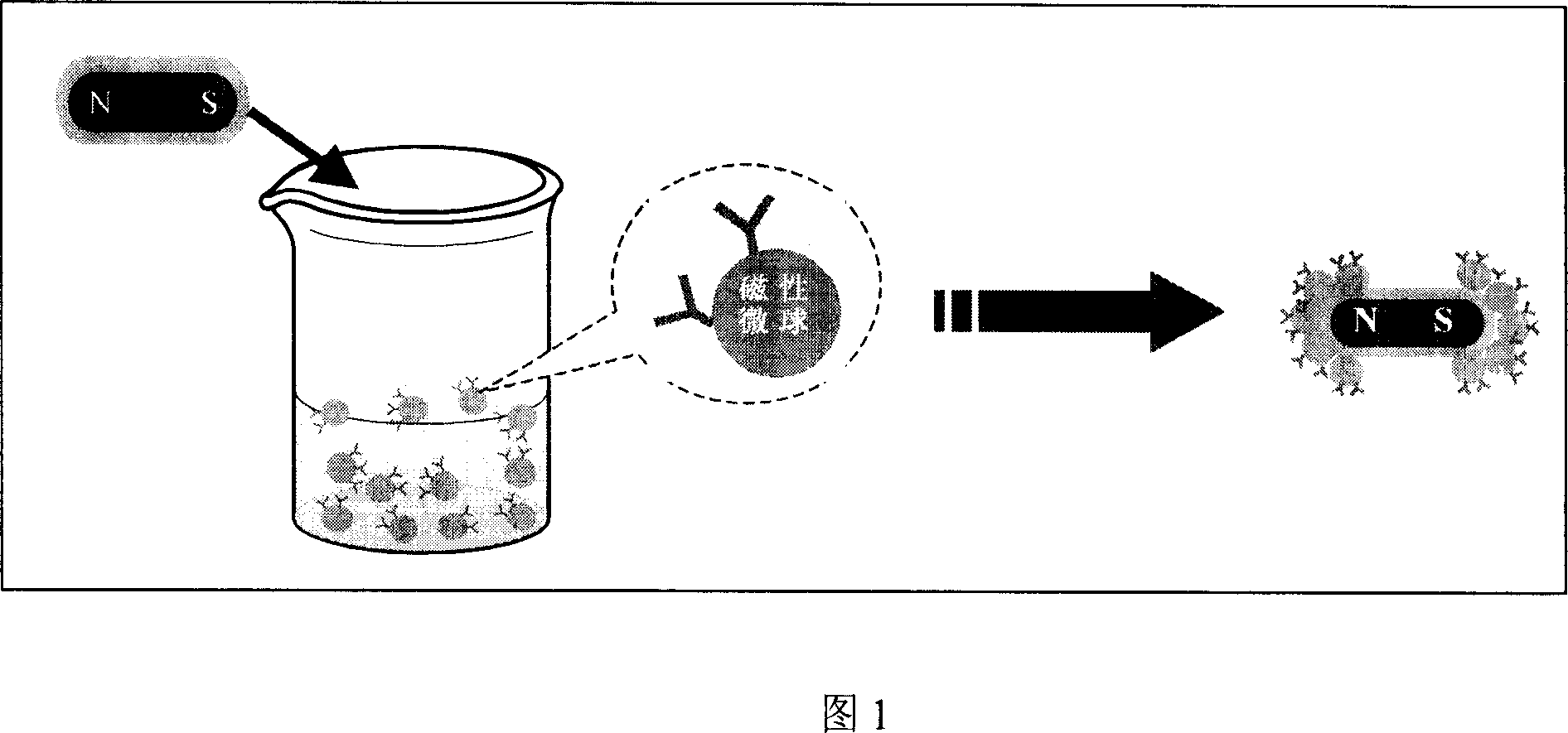
[0045] Example 1: In a 250mL three-necked flask, add 0.5g surface modified ferroferric oxide powder and 200mL deionized water, after ultrasonic dispersion, add 0.2g cetyltrimethylammonium bromide, 2.0g methyl Methyl methacrylate, 0.2g sodium methacrylate, 0.2g ethylene glycol methacrylate, 0.3g potassium persulfate, stirred and emulsified at room temperature and deoxygenated by nitrogen gas, then heated to 70°C, maintaining nitrogen atmosphere and stirring, After 12 hours of reaction, the reaction was stopped, and magnetic poly(methyl methacrylate / acrylic acid) microspheres with carboxyl groups on the surface were prepared. The magnetic microspheres were washed with ethanol / water solution and then dispersed in deionized water to obtain an aqueous dispersion (2.0 wt%) of magnetic poly(methyl methacrylate / acrylic acid) microspheres. The hydrodynamic particle size of the microspheres is 220 nm, and the magnetic content is 15 wt%.
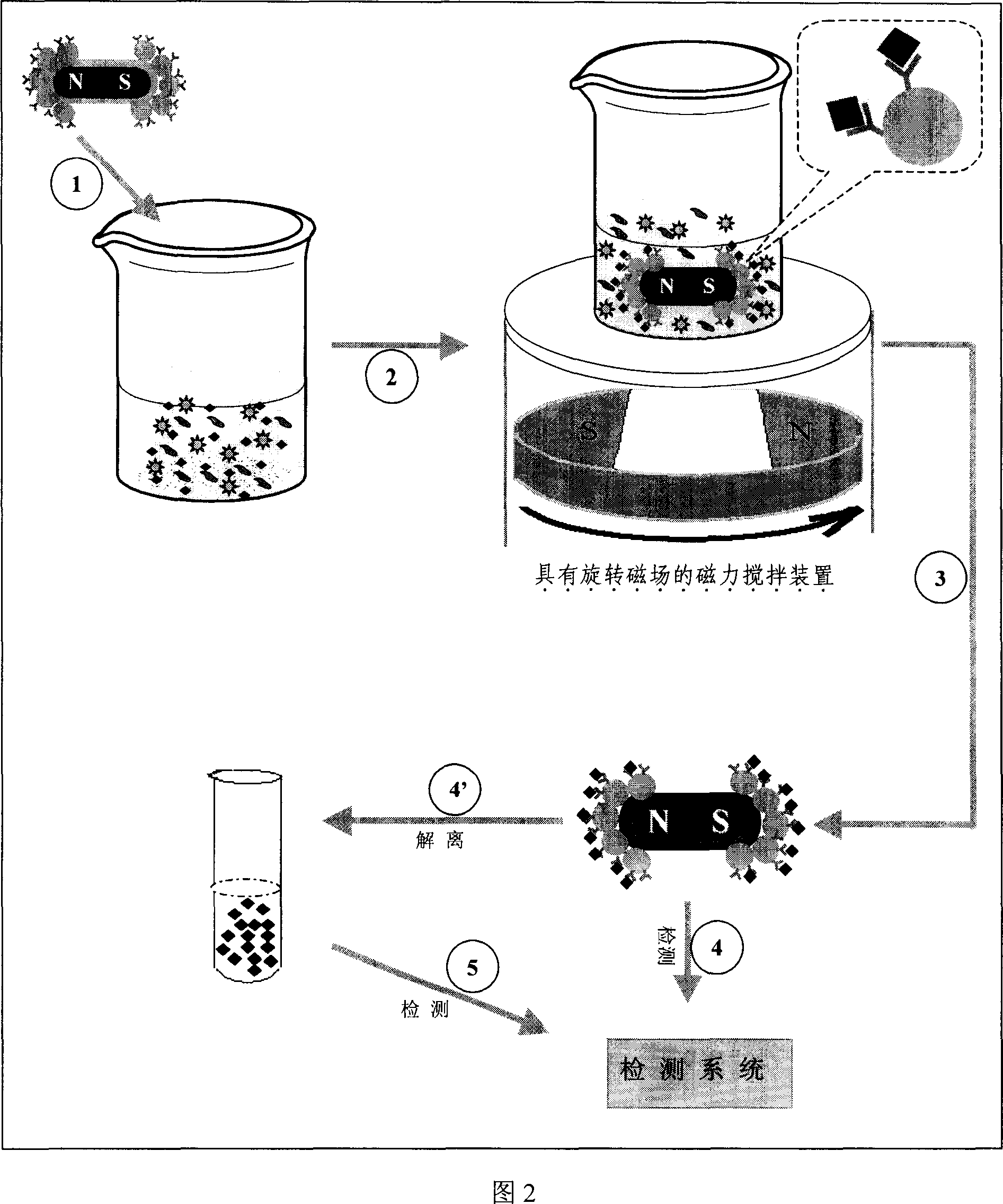
[0046] Into the aqueous dispersion (2.0wt%) of the m...
Embodiment 2
[0047] Example 2: In a 250mL three-necked flask, add 0.5g of surface-modified ferroferric oxide powder and 200mL of deionized water, after ultrasonic dispersion, add 0.2g of cetyltrimethylammonium bromide, 2.0g of methylbenzene Methyl acrylate, 0.2g hydroxyethyl methacrylate, 0.2g diethylene glycol methacrylate, 0.3g potassium persulfate, stir and emulsify at room temperature and deoxidize with nitrogen, then heat to 70℃, maintain nitrogen atmosphere and Under stirring conditions, the reaction was stopped after 12 hours of reaction, and magnetic poly(methyl methacrylate / hydroxyethyl methacrylate) microspheres with hydroxyl groups on the surface were prepared. The magnetic microspheres were washed with ethanol / water solution, and then dispersed in deionized water to obtain an aqueous dispersion (2.0 wt%) of magnetic poly(methyl methacrylate / hydroxyethyl methacrylate) microspheres. The hydrodynamic particle size of the microspheres is 200 nm, and the magnetic content is 12 wt%.
[0...
Embodiment 3
[0049] Example 3: In a 250mL three-necked flask, add 0.02g of ferroferric oxide powder, use 40mL of deionized water and 160mL of absolute ethanol to ultrasonically disperse, and then add 4mL of concentrated ammonia under high-speed stirring (600rpm). After the system was heated to 40°C, 1.00 g of ethyl orthosilicate was added, and after maintaining stirring for 12 hours, 2 mL of r-aminopropyltriethoxysilane (APS) was added, and stirring was continued at 40°C in the dark for 12 hours. The product was centrifuged and washed with ethanol and then deionized water to obtain an aqueous dispersion of magnetic silica microspheres (2.0 wt%). The particle size of the microspheres is 50nm, the surface has amino groups, and the magnetic content is 6.0wt%.
[0050] Into the water dispersion of the magnetic silica microspheres obtained above, a rod-shaped permanent magnet (200G) with a diameter of 0.5cm and a length of 2.0cm covered with polytetrafluoroethylene (200G) was added, and after stirr...
PUM
| Property | Measurement | Unit |
|---|---|---|
| thickness | aaaaa | aaaaa |
| particle diameter | aaaaa | aaaaa |
| particle diameter | aaaaa | aaaaa |
Abstract
Description
Claims
Application Information