Measuring method for concentration of halogen and fluorine compound, measuring equipment thereof and manufacturing method of halogen compound

a technology of halogen and fluorine compound and measuring equipment, which is applied in the direction of mechanical means, instruments, specific gravity measurements, etc., can solve the problems of inconvenient use, large excess of halogen gas, and delay in measuring results, so as to achieve safe and quick determination

Inactive Publication Date: 2002-05-02
SHOWA DENKO KK
View PDF16 Cites 46 Cited by
  • Summary
  • Abstract
  • Description
  • Claims
  • Application Information

AI Technical Summary

Benefits of technology

0171] The present invention relates to indirect measurement of a halogen concentration by bringing the halogen into contact with a metal iodide compound solution to liberate iodine and measuring the liberated iodine by transmittance of visible light. This has made possible continuous measurement of a halogen gas concentration in a reaction gas, which has been difficult until now. By the measurement method of the present invention, the halogen concentration in a halogen compound production plant can be adjusted simply to be a prescribed level economically. The method of the present invention is applicable also to continuous measurement of not only the halogen-containing gas but also of a halogen-oxygen acid salt or the like in an aqueous solution.
0172] Further, the method of measuring a hydrofluorocarbon concentration of the present invention enables safe an

Problems solved by technology

Therefore, the measurement results are obtained with a delay, which is not suitable for controlling the halogen gas concentration in a process at a prescribed level.
However, use of a large excess of the halogen gas is not economical owing to the necessity of a recovery system therefor.
The above method (2), which automates a general method of fluorine determination in a gas, has disadvantages of low response speed owing to relatively long time required for the analysis, complicate maintenance, a relatively large space for the apparatus installation, and so forth.
However, this method involves problems in measurement of a fluorine gas concentration in a fluorine compound production process.
The great heat generation is liable to cause scission of the C--C bond, explosion, or the like, and lowering of the product yield, which are problems in industrial production and operation.
Further, the method has a

Method used


Image

  • Measuring method for concentration of halogen and fluorine compound, measuring equipment thereof and manufacturing method of halogen compound
  • Measuring method for concentration of halogen and fluorine compound, measuring equipment thereof and manufacturing method of halogen compound
  • Measuring method for concentration of halogen and fluorine compound, measuring equipment thereof and manufacturing method of halogen compound

Examples


example 1

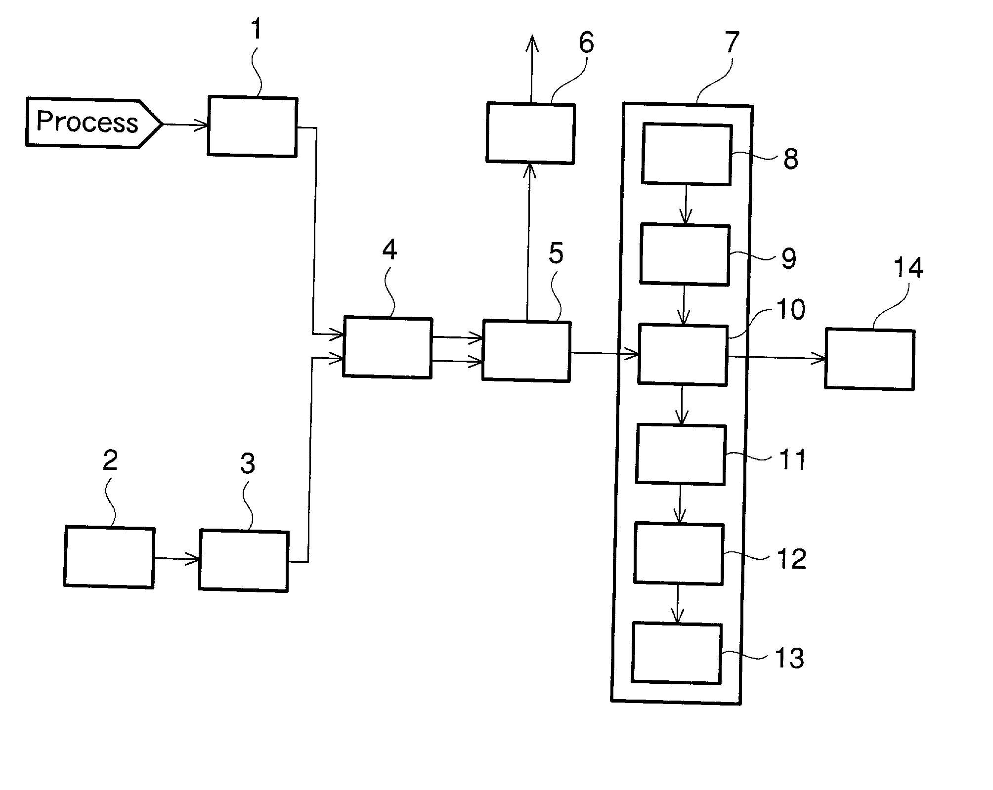
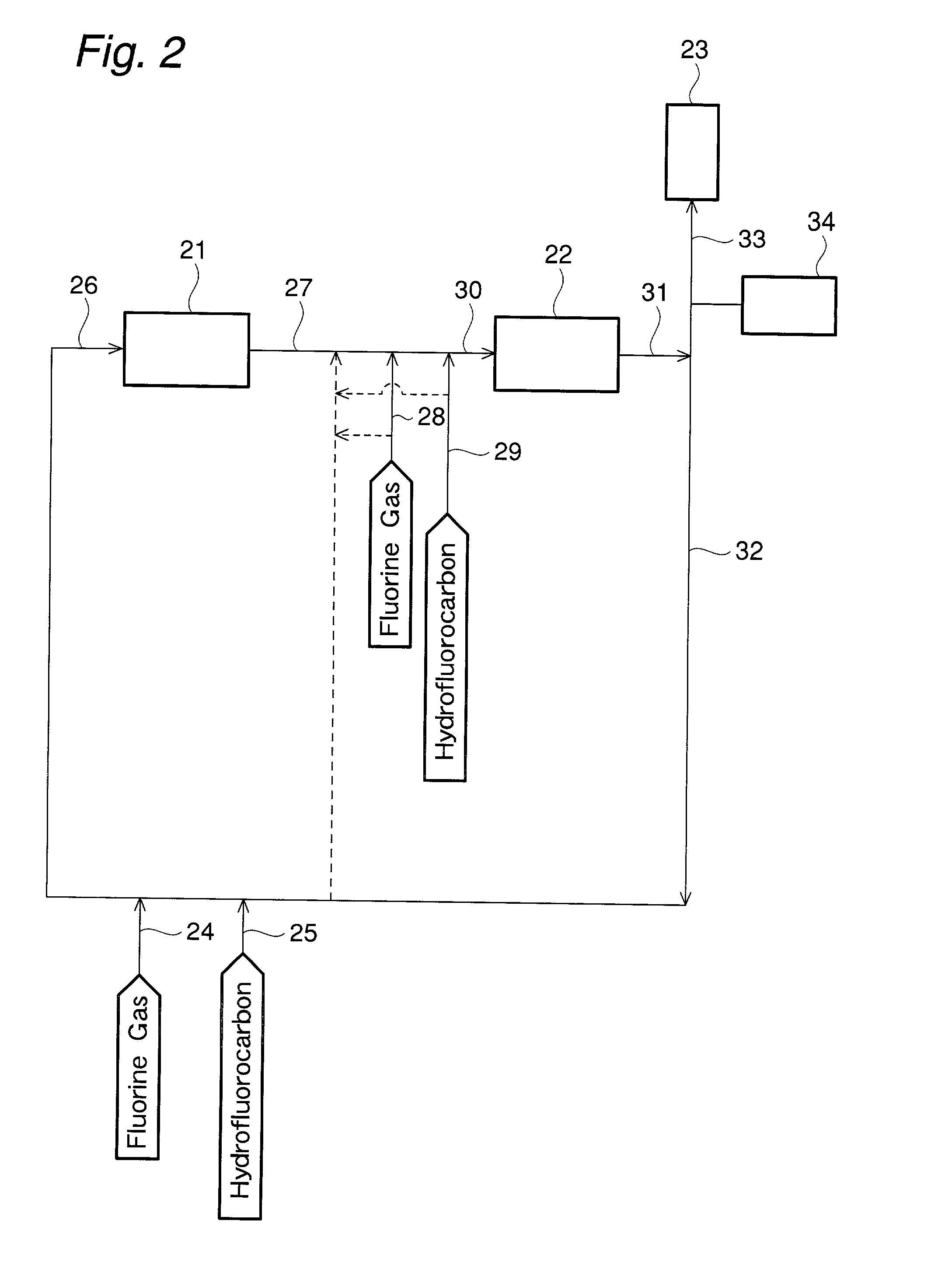
[0181] Trifluoromethane (HFC-23) was directly fluorinated in the presence of a diluent gas in a continuous process to produce tetrafluoromethane (FC-14). The fluorine gas concentration in the process gas under four different conditions was measured with the apparatus shown in FIG. 1. In the measurement, the potassium iodide-starch solution and the process gas were allowed to flow through the reaction section at flow rates of 2 mL / min and 20 mL / min respectively in the same manner as mentioned above. The fluorine gas concentration was derived from the output of the optical sensor, and was also confirmed simultaneously by titration with sodium thiosulfate. The concentration measured by the sodium thiosulfate titration, and the output levels of the optical sensor are shown Table 2 and FIG. 3. The output levels of the optical sensor are on the same line as the standard values shown in FIG. 3, which shows the high reliability of the results of the measurement of remaining fluorine gas con...

example 2

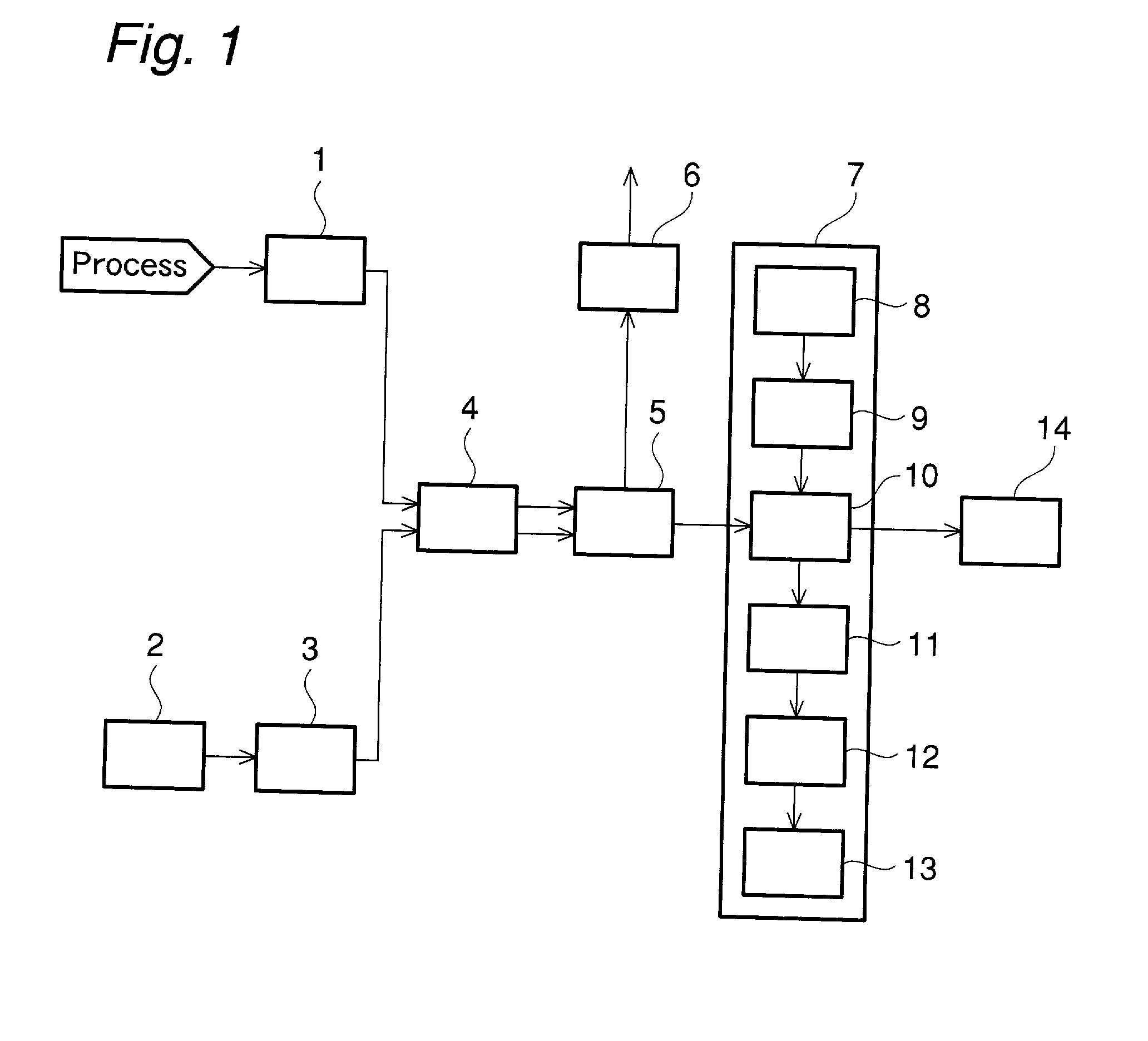
[0182] The process in FIG. 2 for producing perfluorocarbon is explained. Trifluoromethane as the hydrofluorocarbon (25 in FIG. 2) and fluorine gas (24 in FIG. 2) were mixed with a diluent gas (32 in FIG. 2), and the gas mixture (26 in FIG. 2) was introduced into a first reaction zone (21 in FIG. 2). In the first reaction zone, the reaction was allowed to proceed under the conditions of the reaction pressure of 1.5 MPa, the reaction temperature of 400.degree. C., the molar ratio of F.sub.2 / trifluoromethan-e of 1.51, and the trifluoromethane concentration at the inlet of 2.1 mole % to obtain an outlet gas (27 in FIG. 2) of the first reaction zone.

[0183] To this outlet gas, 1,1,1,2-tetrafluoroethane as a new hydrofluorocarbon (29 in FIG. 2), and fluorine gas (28 in FIG. 2) were added. The gas mixture (30 in FIG. 2) was introduced to a second reaction zone (22 in FIG. 2). In the second reaction zone, the reaction was allowed to proceed under the conditions of the reaction pressure of 1....

example 3

[0184] A reactor employed had an inner diameter of 20.6 mm. a length of 500 mm, being made of inconel 600, being of an electric heater type, and having been passivated by fluorine gas at 600.degree. C. The reactor was heated to 280.degree. C. with passage of a diluent gas (composed of 41.8 vol % of tetrafluoromethane as a perfluorocarbon, and 58.2 vol % hydrogen fluoride) at a flow rate of 50 NL / h. To one portion of the separated diluent gas flow, 1,1,1,2-tetrafluoroethane was introduced as a hydrofluorocarbon at a flow rate of 1.0 NL / h. Similarly, to the other portion of the separated diluent gas flow, fluorine gas was introduced at a flow rate of 2.0 NL / h to cause direct fluorination. A part of the reactor inlet gas was introduced into a heated measurement cell (window material: calcium fluoride) by an automatic switching valve made of SUS316 driven pneumatically, and was subjected to infrared spectrum measurement by an infrared spectrophotometer.

[0185] Table 4 shows the infrared ...


PUM


Abstract

The present invention provided a method for measuring a halogen gas and/or a hydrofluorocarbon for the purpose of controlling the concentration of the halogen gas and/or the hydrofluorocarbon, in a plant producing a halogen compound or a perfluorocarbon, at a predetermined concentration level quickly, easily, and precisely for the control. The present invention provides also a measurement apparatus for the above measurement which has a compact structure, and in which the parts are exchangeable quickly and readily. The present invention provides further a process for producing a halogen compound or a perfluorocarbon employing the measurement method and the measurement apparatus. In particular, the present invention intends to provide a method for measuring safely and quickly a hydrofluorocarbon concentration in a mixed gas stream in a process of producing a perfluorocarbon by direct fluorination reaction of a hydrofluorocarbon and F2.

Description

[0001] This application is an application filed under 35 U.S.C. .sctn.111(a) claiming benefit pursuant to 35 U.S.C .sctn.119(e)(1) of the filing date of Provisional Applications 60 / 1216,519 and 60 / 216,517 both filed on Jul. 6, 2000 pursuant to 35 U.S.C. .sctn.111(b).[0002] The present invention relates to a method for measuring a concentration of a halogen and / or a fluorine compound in a gas, a measurement apparatus therefor, and a process for producing a halogen compound employing the measurement apparatus.[0003] Iodometry is known as a method for determining the concentration of a halogen gas. The iodometry is a widely employed titration method for determining a halogen indirectly by oxidizing the iodine ion, a weak reducing agent, with a halogen, a strong oxidizing agent, to iodine, and titrating the liberated iodine. The iodometry is applicable to quantitative determination of a halogen such as chlorine and fluorine, and oxygen acid salts thereof.[0004] A measurement apparatus e...

Claims


Application Information

Patent Timeline
IPC IPC(8): G01N33/00
CPCY10T436/19G01N33/0052
Inventor OHNO, HIROMOTOOHI, TOSHIOKAGA, KAZUNARITACHI, RYUICHIMATSUDA, ITSUAKI
Owner SHOWA DENKO KK
Why Eureka
Try Eureka