Apparatus for removing photoresist film

a technology of resist film and apparatus, which is applied in the direction of cleaning using liquids, photosensitive materials, instruments, etc., can solve the problems of high cost of oxygen gas plasma generation apparatus, high risk of needing to heat strong sulfuric acid up to 150.degree. c,

Inactive Publication Date: 2002-08-22
AGILENT TECH INC
View PDF8 Cites 7 Cited by
  • Summary
  • Abstract
  • Description
  • Claims
  • Application Information

AI Technical Summary

Problems solved by technology

However, there had been some problems in this method [1], including the requirement of an expensive apparatus for generating the oxygen gas plasma, a potential of damaging the substrate containing an electrical element due to the presence of a charge carrier in the plasma, and the like.
When using hot concentrated sulfuric acid, however, there has a disadvantage, such as an extremely high risk of a necessary for heating strong sulfuric acid up to 150.degree. C.
However, as shown in the above schemes (1) and (2), this method [2] has a problem that, since a sulfuric medium is diluted with water produced every addition of hydrogen peroxide to hot concentrated sulfuric acid, the concentration of hot concentrated sulfuric acid after mixing is decreased with time.
The method [2] also has disadvantages, including the extremely high risk as described for the method [1], i.e. the use of strong sulfuric acid at an elevated temperature, and the exothermic heat ...

Method used


Image

  • Apparatus for removing photoresist film
  • Apparatus for removing photoresist film
  • Apparatus for removing photoresist film

Examples


embodiment 1

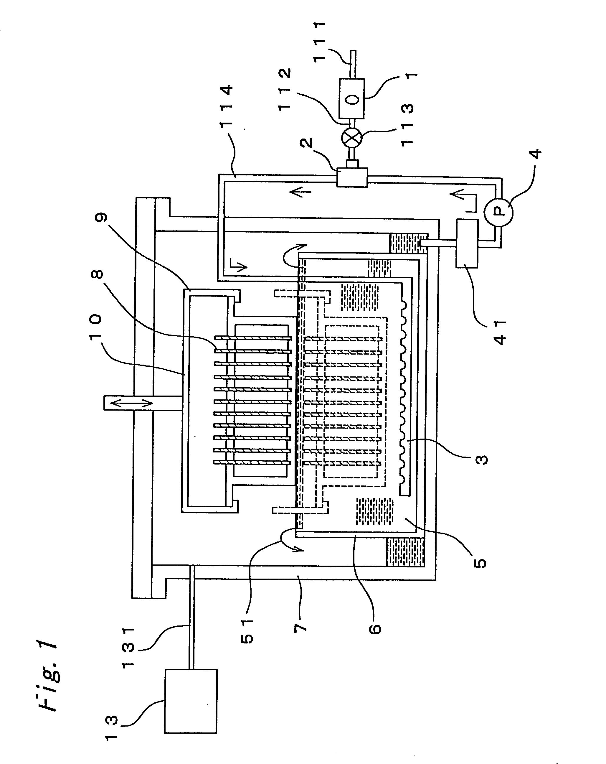
[0042] The embodiment 1 relates to a method of removing a photoresist film using an apparatus for removing a photoresist film (A1, FIG. 1) as the second aspect of the invention.

[0043] In the present application, the photoresist film to be removed may include either a film formed from a photoresist material containing an organic polymer compound, which the photoresist material is used in any processes of manufacturing semiconductor devices, a film decomposed by heating, a film of which the surface is modified by heating or heavy doping, or a film having a surface on which an inorganic substance is deposited in an etching process.

[0044] The substrate of which the surface has the photoresist film may include silicon wafer, a glass substrate for a liquid crystal display device, a glass-reinforced epoxy substrate used for producing a printed-circuit, and the like, but is not particularly limited thereto as long as it may be any one commonly used in the manufacture of semiconductor device...

embodiment 2

[0072] The above embodiment 1 illustrates the method and the apparatus of moving the substrate itself in order to change the relative position of the surface of the substrate and the liquid surface of the solution. The present invention, however, also provides another method and apparatus which can change the liquid surface of the photoresist film removing solution to control the relative position. FIG. 4 shows an apparatus which is able to change the liquid surface of the solution to control the relative position.

[0073] The apparatus (A2) shown in FIG. 4 has a constitution typically similar to that of the apparatus (A1) shown in FIG. 1 (that is, the raw gas is a oxygen-containing gas, and any of the photoresist film removing solution described in embodiment 1 may be used). In the apparatus (A2) of embodiment 2, however, it is not essential to move the substrate 8 vertically using the cassette carrier unit 10 in the sealed container 7. An automatically operated valve 61 is equipped ...

embodiment 3

[0076] The present invention also provides a different method and apparatus other than those described above embodiments 1 and 2, further including an ultrasound generating means in the apparatus, and applying ultrasonic vibration to the photoresist film removing solution containing the ozonized gas and the substrate using the ultrasound generating means, in order to improve the efficiency of the process capacity.

[0077] FIG. 5 illustrates an example of an apparatus of removing a photoresist film (A3) used in this embodiment 3, wherein most of the apparatus may be the same as that described in this embodiment 1, with the exception of an element and a function specifically described).

[0078] The ultrasound generating means 71 used in the apparatus (A3) of the embodiment 3 may be one that is well known in the prior art. The ultrasound generating means 71 is laid adjacent to the bottom of the sealed container 7 in FIG. 5, but is not limited thereto. As long as the ultrasonic vibration ca...


PUM

PropertyMeasurementUnit
Levelaaaaaaaaaa

Abstract

A method of removing photoresist film with high efficiency of removal and friendliness with the environment while reducing the material consumption and the cost for the ventilation facility, and an apparatus used for the method are provided. Particularly the present invention provides a method of removing a photoresist film provided on a surface of a substrate, comprising steps of in a sealed system, disposing the substrate surface having the photoresist film to contact with a photoresist film removing solution, making ozone exist in gas phase and/or solution phase in the vicinity of the liquid surface of the photoresist film removing solution, and changing a relative position between the surface of the substrate and the liquid surface of the solution to decompose or remove the photoresist film from the substarate, characterized in that the relative position is changed continuously or intermittently within a range between a position where a bottom edge of the substrate is present above the liquid surface of the solution, and another position where a top edge of the substrate is present below the liquid surface of the solution. The present invention also provides an apparatus used for the method.

Description

[0001] This application is a continuation application of PCT international application No. PCT / JP99 / 06323 which has an international filing date of Nov. 12, 1999 which designated the United States, the entire contents of Which are incorporated by reference.[0002] The present invention relates to a method of removing a film containing an organic composition and, more particularly, to a method of removing a photoresist film containing an organic polymer compound used in a photolithographic process for producing a semiconductor device and the like, and to an apparatus used in the method.DESCRIPTION OF THE RELATED ART[0003] A photoresist material is generally used in a photolithographic process for forming a fine pattern and / or in a subsequent etching step for forming an electrode pattern in course of manufacturing a semiconductor device, such as an integrated circuit, a transistor, a liquid crystal device, a diode and the like.[0004] For example, when a silicon oxide layer is formed in...

Claims


Application Information

Patent Timeline
IPC IPC(8): G03F7/42H01L21/00
CPCG03F7/42G03F7/422G03F7/423G03F7/428H01L21/67075Y10S134/902
Inventor OYA, IZUMINODA, SEIJIMIYAMOTO, MAKOTOKUZUMOTO, MASAKIOHMORI, MASASHIKATAOKA, TATSUO
Owner AGILENT TECH INC
Why Eureka
Try Eureka