Electrochemical treating method such as electroplating and electrochemical reaction device therefor

a technology of electrochemical treatment and electrochemical reaction, which is applied in the direction of electrochemical machining apparatus, surface reaction electrolytic coating, crystal growth process, etc., can solve the problems of large scale, ineffective use of surface active agent, and inability to treat liquid waste, so as to reduce the amount of liquid waste to be treated, the diffusion constant is high, and the effect of enhancing the reactability

Inactive Publication Date: 2003-01-30
YOSHIDA +2
View PDF0 Cites 27 Cited by
  • Summary
  • Abstract
  • Description
  • Claims
  • Application Information

AI Technical Summary

Benefits of technology

0036] According to one aspect of the present invention, reaction is executed in a vessel containing matter shifted into a supercritical or subcritical state and an electrolytic solution. The expression "supercritical state" herein used refers to a state which is kept under a temperature / pressure higher than the critical point indicated in an entropy chart of temperature and pressure in a phase diagram. The matter shifted in this state is not in the form of gas nor liquid. According to this means, the reaction vessel is equalized in quality by the supercritical matter having a high diffusion constant and ion is efficiently supplied to the peripheral area of the electrode, etc., thereby enhancing the reactability. Moreover, since a small amount of electrolytic solution is good enough, the amount of liquid waste to be treated can be suppressed.

Problems solved by technology

However, the surface active agent is actually not used because of its high price, complicated process, etc.
Also, in the technical field of electrochemical reaction such as electroplating, etc., there is encountered with a problem of treatment of liquid waste such as used-plating solution.
However, this method is, in many cases, executed using a large scaled-equipment which, in general, cannot be said very efficiency and it cannot fully cope with the problem of treatment of liquid waste under the recent increasing strict restriction by rules and regulations.
Thus, it gives rise to a problem that the process becomes complicated.
Moreover, the solution used for cleaning becomes a large quantity of liquid waste and this again raises the above-mentioned problem of treatment of liquid waste.
Therefore, a plurality of vessels and work spaces for them are required which results in high cost of the equipment.
Moreover, a poor working environment is created where work must be done under such circumstance that the treatment solution is scattered and hazardous gases are generated.
In addition, since it takes a long time for immersing the matter to be treated in the treatment solution, productivity is lowered.
However, all of them require the use of chemicals and special equipment.
Therefore, much time is required for them to break water.
Therefore, in the case where an electroplating product having a larger capacity than the above-mentioned chamber is to be cleaned, the consumption of carbon dioxide is increased, thus making the method of using this conventional apparatus expensive.
Moreover, it can be expected that the working environment is deteriorated due to discharge of carbon dioxide.
Thus, this conventional apparatus is difficult to be actually put into practice.
This makes the equipment cost high.
In addition, the consumption of water is increased.
Moreover, it is very troublesome and labor consuming to recollect the plating solution (so-called pumping back) at the time of taking the matter to be plated out of the plating vessel.
In addition, since the recollected solution must be condensed, productivity is very low.
On the other hand, the conventional plating technique is generally poor in adhesion power of plating and the plating is hardly adhered to the reverse side and recessed part of the matter to be treated where electric current density is low.
Accordingly, this conventional plating technique cannot cope with the requirement for plating a deformed matter.
Much time is required for this succeeding treatment process and so productivity is low.
Moreover, the liquid waste discharged from plating factories is restricted in its quality by laws.
However, the conventional discharged liquid waste treatment requires expensive equipment, various kinds of chemicals, a large amount of water and much time, and its productivity is very low.
As a result, plating omission and non-uniform plating occur.
Moreover, since electric energy is consumed due to generation of the gases and the smooth plating treatment is jeopardized to that extent, the electric current efficiency is lowered.
In the electroless plating, however, hydrogen gas, etc. are necessarily generated with the progress of depositing reaction of plating and the method for suppressing the generation of gas is not practically usable because the suppression of the generation of gas adversely affects the deposition of plating, thus making it unable to execute the plating treatment itself.
Accordingly, it is practically impossible to employ the electroless plating treatment method which allows the generation of hydrogen gas, etc. to the electroplating treatment, etc.
This prevents the smooth flow or passage of electric current through the electrolytic solution and makes it difficult to execute the electroplating treatment.
Thus, the above method is unable to be applied to the electroplating treatment.

Method used


Image

  • Electrochemical treating method such as electroplating and electrochemical reaction device therefor
  • Electrochemical treating method such as electroplating and electrochemical reaction device therefor
  • Electrochemical treating method such as electroplating and electrochemical reaction device therefor

Examples


specific example 2

[0167] A pure copper plate was used for the anode electrode and a Hull cell test-use brass plate was used for the cathode electrode, and electroplating was carried out. A copper cyanide bath was used as the electrolytic solution. Its composition is shown hereunder.

[0168] [Plating Bath Composition]

3 primary copper cyanide: 30 g / l sodium cyanide: 45 g / l (free sodium cyanide): 15 g / l sodium carbonate: 15 g / l pH: 12.5

[0169] As the surface active agent, block polymer (PEO-PBO, molecular weight=860-b-660 g / mol) of polybutyleneoxide-polyethyleneoxide was added by 1.5 wt % based on the above electrolytic solution.

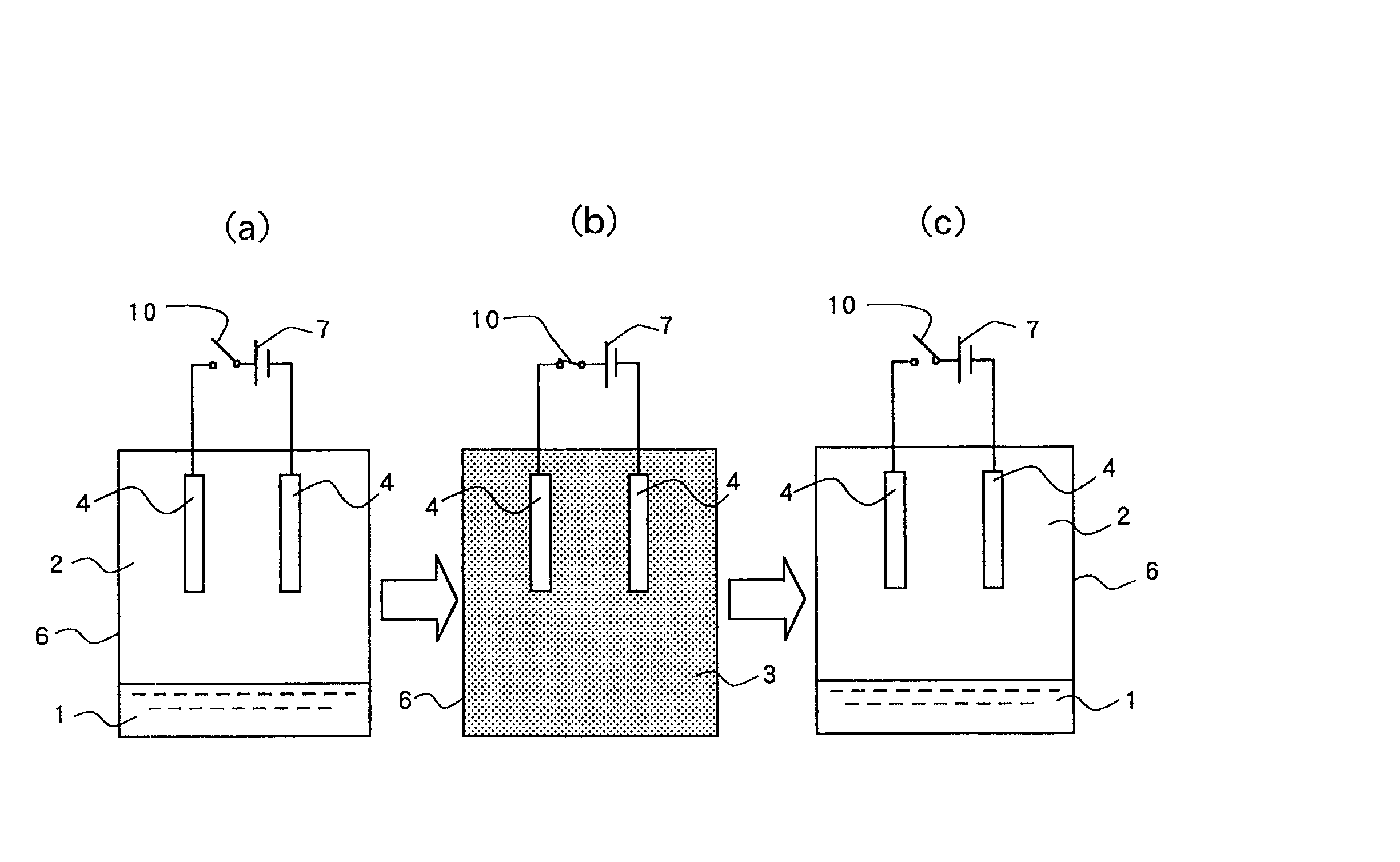
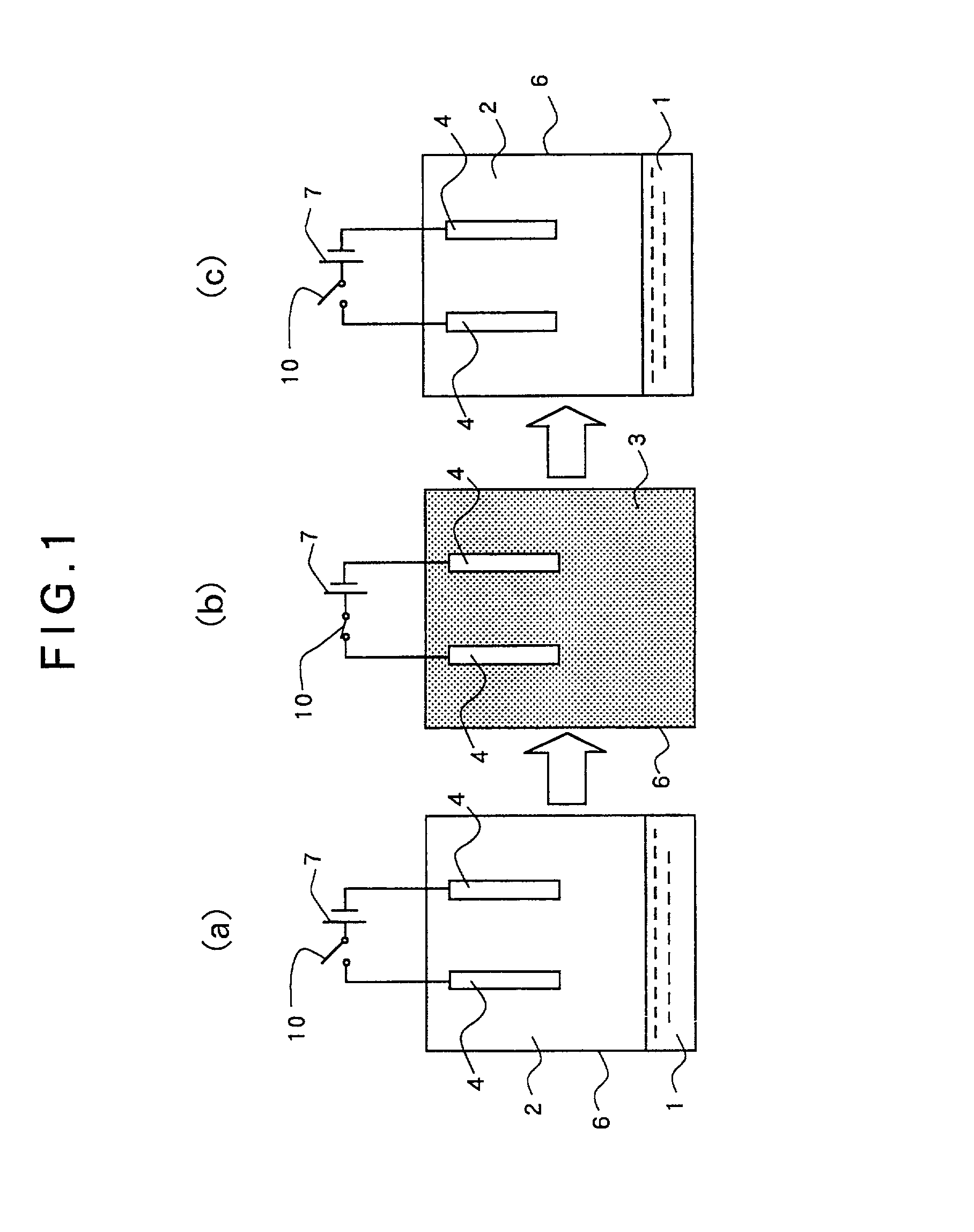
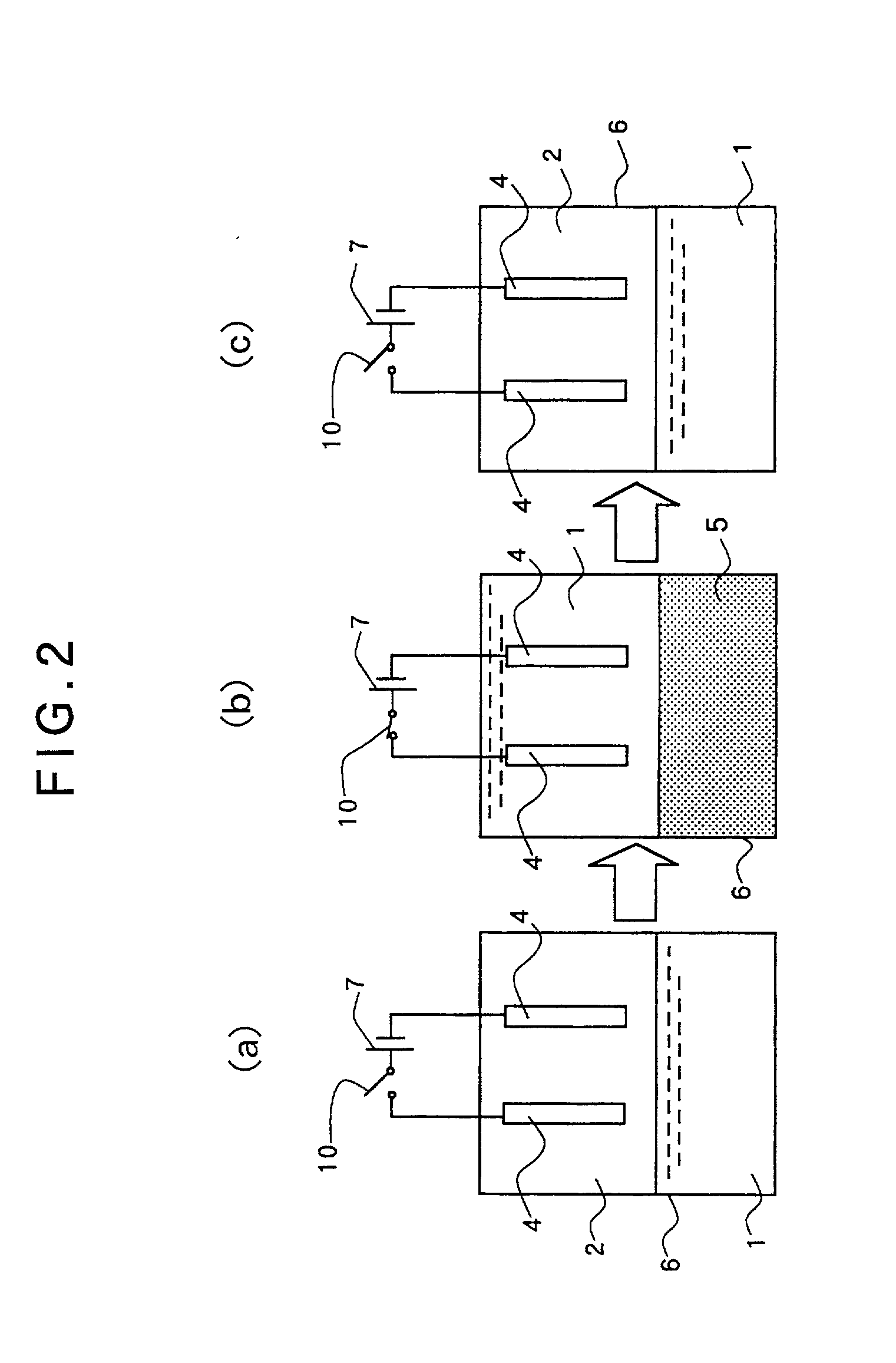
[0170] Carbon dioxide was used as the matter to be shifted into a supercritical state, and the volume ratio of the electrolytic solution and the carbon dioxide was set to 1 / 2 under the normal pressure. Reaction was carried out for 10 minutes under the conditions of temperature of 50 degrees C. (323 K), pressure of 15 MPa and electric current density of 5 A / dm.

[0171] As a result, a ...

specific example 3

[0175] A zinc plate was used for the anode electrode and a Hull cell test-use brass plate was used for the cathode electrode, and electroplating was carried out. A zincate bath was used as the electrolytic solution. Its composition is shown hereunder.

[0176] [Plating Bath Composition]

5 zinc oxide: 40 g / l sodium hydroxide: 180 g / l pH: 5.1

[0177] As the surface active agent, block polymer (PEO-PBO, molecular weight=860-b-660 g / mol) of polybutyleneoxide-polyethyleneoxide was added by 1.5 wt % based on the above electrolytic solution.

[0178] Carbon dioxide was used as the matter to be shifted into a supercritical state, and the volume ratio of the electrolytic solution and the carbon dioxide was set to 1 / 2 under the normal pressure. Reaction was carried out for 10 minutes under the conditions of temperature of 50 degrees C. (323 K), pressure of 15 MPa and electric current density of 5 A / dm. As a result, a uniform zinc film was formed on the surface of the cathode electrode with a good powe...

specific example 4

[0182] A copper plate was used for the anode electrode and a Hull cell test-use brass plate was used for the cathode electrode, and electroforming was carried out. A copper sulfate bath was used as the electrolytic solution. Its composition is shown hereunder.

[0183] [Copper Sulfate Bath]

7 copper sulfate: 200 g / l phosphoric acid: 60 g / l hydrochloric acid: 30 mg / l pH: 4.5

[0184] As the surface active agent, block polymer (PEO-PBO, molecular weight=860-b-660 g / mol) of polybutyleneoxide-polyethyleneoxide was added by 1.5 wt % based on the above electrolytic solution.

[0185] Carbon dioxide was used as the matter to be shifted into a supercritical state, and the volume ratio of the electrolytic solution and the carbon dioxide was set to 1 / 2 under the normal pressure. Reaction was carried out for 10 minutes under the conditions of temperature of 50 degrees C. (323 K), pressure of 15 MPa and electric current density of 20 A / dm.

[0186] As a result, a uniform electroformed copper film was formed...


PUM

PropertyMeasurementUnit
pressureaaaaaaaaaa
temperatureaaaaaaaaaa

Abstract

A novel method of electrochemical treatment such as electroplating, etc. and an electrochemical reaction apparatus thereof which is high in reactability and able to be electrochemically reacted efficiently, which is small or zero in amount of generation of liquid waste such as electrolytic solution and cleaning liquid and therefore, amicable to the environment, and in which it is no more required to clean the electrode, etc. with cleaning liquid after reaction. Electrochemical reaction is executed in a reaction vessel (6) containing matter (5) which is in a supercritical or subcritical state and an electrolytic solution (1), and after reaction, the supercritical or subcritical matter (5) is shifted into a state of the matter (5) before being shifted into a critical state.

Description

[0001] This invention relates to a method of electrochemical treatment such as electroplating, etc. and an electrochemical reaction apparatus thereof, which method and apparatus are suited to be used for electrochemical treatment such as, for example, electroplating, and the like, which method and apparatus are capable of executing various treatment processes safely, rationally and rapidly, using supercritical or subcritical matter such as, for example, carbon dioxide, which method and apparatus are capable of processing the used-carbon dioxide, treatment solution, etc. rationally and rapidly, which method and apparatus are capable of suppressing the consumption of the amount of the acid picking solution, plating solution, etc. and reducing the amount of liquid waste generated from the plating operation thereby preventing the pollution of the environment and achieving the improvement of the working environment, the enhancement of productivity and the reuse of the liquid waste, which...

Claims


Application Information

Patent Timeline
Patent Type & Authority Applications(United States)
IPC IPC(8): B23H3/08C23C18/16C23C22/24C23C22/73C25D3/02C25D5/00C25D5/34C25D5/48C25D11/02C25D11/04C25D13/00C25D17/02C25F3/00
CPCB23H3/08C23C18/1685C23C22/24C23C22/73C25D3/02C25D5/34C25D5/48C25D11/02C25D11/04C25D13/00C25D17/02C25F3/00C25D5/003C25D11/005C23C22/18
Inventor YOSHIDA, HIDEOMIYATA, SEIZOASAI, YOSHIHIROSONE, MASATOIWAO, FUMIKOASAI, HIROE
Owner YOSHIDA
Why Eureka
Try Eureka