As the need for smaller and smaller coated particles increases, the principle barrier to achieving uniform, contiguous coating has been the tendency for particles below 10 to 15 microns to severely
agglomerate and clump.
Ordinary horizontal fluidized beds and
barrel coaters are simply unable to overcome the strong interparticulate attractors, such as van der Waals forces, that increase with decreasing particle diameters.
Few of the prior art methods and apparatus are capable of effectively coating contiguous and homogeneous coatings on Geldart Class C powders.
This benefit, however, is considerably offset by the principal limitations of fluidized beds: agglomeration and bonding of the powders.
As is well-known, for example, when fluidized beds are used for the production or coating of very fine powders, particles in the
bed are susceptible to (a) agglomeration by van der Waals and other interparticulate
attractor forces and / or (b)
sintering or cementing together of particles by the coating being deposited on their surfaces at high temperature.
If these agglomerated or sintered particles are not continuously broken apart, their points of contact prevent complete coating and the lumps may tend to grow and settle to the bottom of the fluidizing
bed, greatly reducing
effective surface areas.
Because most coated
powder applications require complete and homogeneous coating
layers, the foregoing factors prevent the use of all but a small number of the methods and apparatus taught in the prior art.
Even such reactors, capable of fluidizing, deagglomerating, and coating uniform Geldart Group C particles, are challenged beyond their capabilities of coating contiguous and homogeneous coatings in many practical industrial situations.
For example, an important limitation of the RFFB-CVDR and other high gas-shear reactors is that the gas-
stream deagglomeration principle fundamentally requires high gas
stream velocities.
This occurs because
small particles that are expelled from the top of the
bed have high velocities that require greater distance to slow down and turn around to return to the bed.
The
elutriation phenomenon leads to a major limitation of the RFFBCVDR.
Thus, heavy
powder particles averaging below about 0.5 microns and light density particles averaging below about 5 to 10 microns contain major percentages of particles that are extremely difficult to separate from gas streams which overload the particulate collection systems and rapidly clog them.
When it is a primary objective to coat smaller Geldart Class C powders, as in the case of Tough-Coated Hard Powders (TCHP), operating this equipment was traditionally difficult to impossible.
It has been demonstrated using the RFFB-CVDR equipment on commercially-available 2-micron
titanium nitride core powders, that nanofines quickly overload and clog the dust collection and
filtration system.
Avoiding this condition requires an expensive and quality-degrading (
oxygen-inducing) Stokes Law
sedimentation classification process to separate the fines and substantially reducing the yield of the incoming core powders.
Another major
disadvantage is that the RFFB-CVDR, which operates in turbulent gas flow
fluidization conditions, cannot be scaled down to smaller-
diameter, smaller-capacity fluidized beds for research and development and for high-value products.
Test increments of different coating weight percentages of the intermediate and binder coatings, plus test increments of extremely expensive core powder such as cubic
boron nitride or
diamond, or test increments involving different carbon percentages all become practically and economically out of reach because milling in test increments breaks off the coatings and blending has been found to be highly ineffective at these grain sizes.
Yet another major
disadvantage of the RFFB-CVDR occurs when it is used to coat small and / or very light density Geldart Class C powders with 50-75 wt % of
tungsten, for example.
It has been found that this reduced uniformity of the coating thickness on both large and
small particles in the distribution has a potentially severe effect.
Still another major disadvantage of the RFFB-CVDR is that as the smaller particles are separated, collected, and recirculated into the
reaction zone, they cool and must be reheated,
wasting the
heat energy gained in the
reaction zone.
Finally, this long
residence time of the nanoparticles outside the hot
reaction zone varies according to the amount of powder in the lot, creating two other major disadvantages.
The key barriers to wider use of these methods include removal of the liquid media after coating, residual salts or other products, oxidation, and coagulation of the coated powders.
This may become a trend with increasing numbers of
core particle materials, but producing such uniform powders of many different
ceramic materials is in itself a highly challenging scientific endeavor.
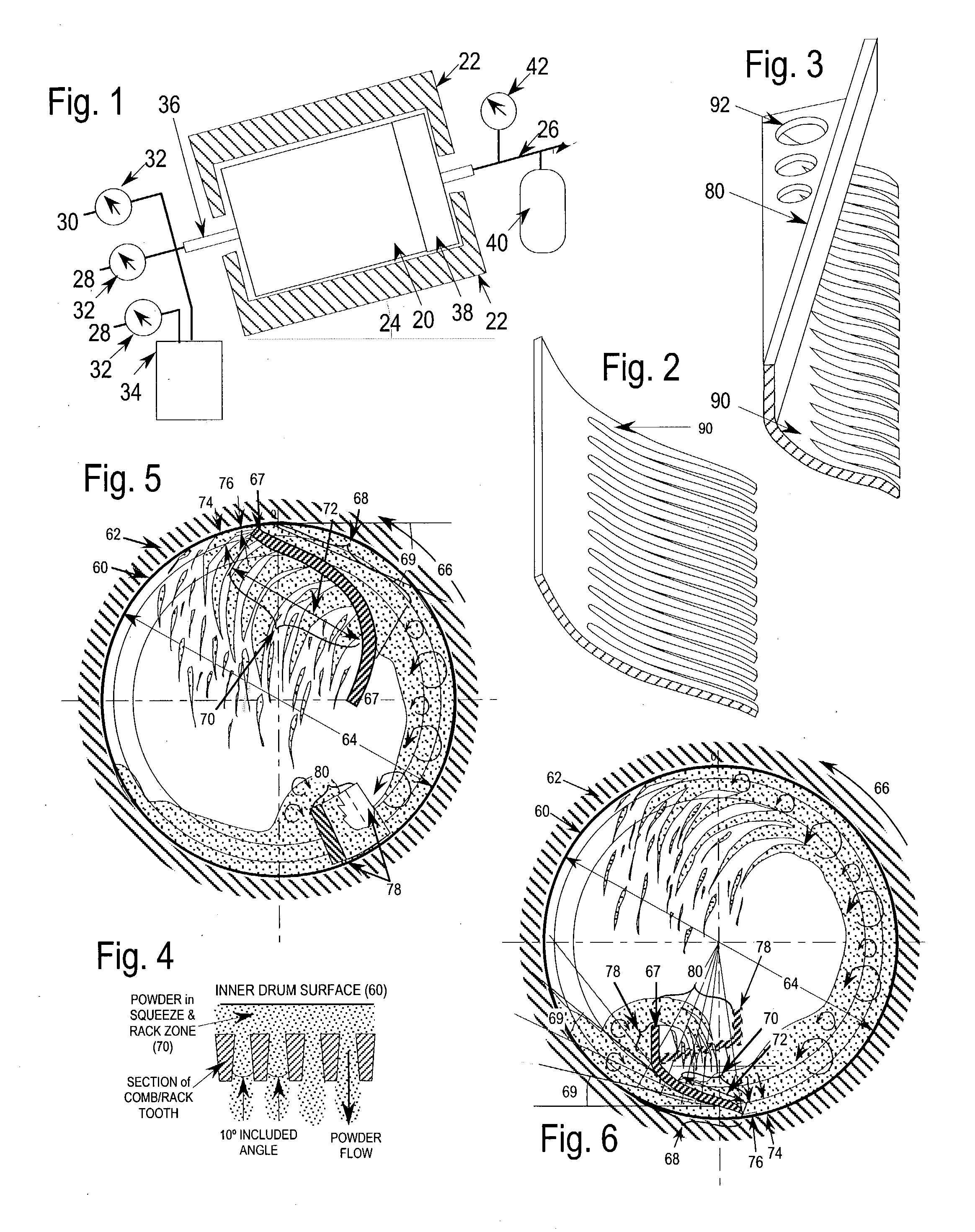
While not wishing to be limited, it is believed that the non-uniform compression provides a flow gradient to the
particulate material flowing through the elongated apertures.
The non-uniform compression is sufficient to force the particulate material to flow through the elongated apertures resulting in shear and tensile forces being applied to the particulate material.
As stated, one problem typically associated with treating Geldart class C or larger powders of metal, binder, ceramic, or polymer is the tendency of such powders to
agglomerate, and thus not be uniformly treated.
The non-uniform compression is suitably applied to the particulate matter such that it forces the particulate material to flow through the elongated apertures resulting in shear and tensile forces being applied to the particulate material.
In certain circumstances, the non-uniform compression provides a flow gradient to the particulate material flowing through the elongated apertures.
If the rotational speed is too high, the comb and its support may be overloaded and the powder may "cake" excessively on the walls of the drum due to excessive g-forces and squeezing by the comb.
The non-uniform compression should be in an amount sufficient to force the particulate material to flow through the elongated apertures resulting in shear and tensile forces being applied to the particulate material.
Additional non-uniform compression may be applied to the particulate material by forcing the particulate material between the structural support portion of the contacting member.
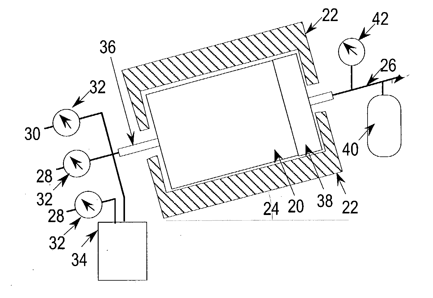
The prior art describes problems in the homogenization of powders coated with a CVD process.
For example, premature CVD coating generally occurs at the reactant gas inlet.
However, too short a length decreases the amount of heat that can be supplied to the surface of the drum at the periphery.
On the other hand, too long a drum length decreases homogeneity and
fluidization efficiency.
The ceramic or metallic filter cannot be placed inside the
rotating drum reactor because the powder cascading from above would quickly clog, e.g., within minutes.
In fact, left unchecked, the agglomerates tend to classify themselves according to size, further hindering homogeneous
processing.

