
Epoxy resin compositions, solid state devices encapsulated therewith and method

Inactive Publication Date: 2004-04-08
GENERAL ELECTRIC CO
View PDF6 Cites 41 Cited by
  • Summary
  • Abstract
  • Description
  • Claims
  • Application Information

AI Technical Summary

Benefits of technology

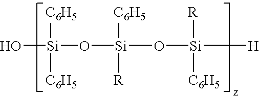
[0014] The inventors of the present invention have determined that by using siloxane surfactants it is possible to compatibilize silicone resins with epoxy resins to make an encapsulant for a solid state device which has clarity, optimum glass transition characteristics, desirable thermal expansion characteristics, moisture resistance, refractive index values as well as transmission characteristics at particular wavelengths. The encapsulant composition comprises (A) at least one silicone resin, (B) at least one epoxy resin, (C) at least one anhydride curing agent, (D) at least one siloxane surfactant, and (E) at least one ancillary curing catalyst. Coatings using these encapsulant compositions provide moisture penetration resistance as well as heat resistance. The obtained composition may also be used as adhesives and dielectrics for multichip module fabrication. The adhesive is used for attaching chips onto a substrate or flex, as an adhesive for laminating a dielectric film such as Kapton, and as a dielectric or top layer providing a moisture resistant and abrasion resistant protection layer. The obtained formulations may also be used as encapsulants for embedding devices in multichip module fabrication.
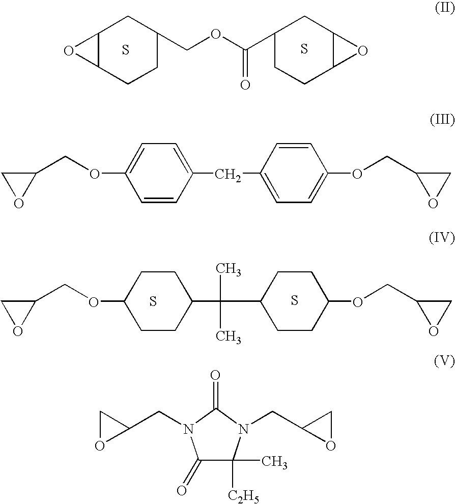
[0020] Additives such as thermal stabilizers or antioxidants maybe used with aromatic epoxy resins to lessen discoloring. Flexibilizers are useful in the composition to reduce brittleness and include aliphatic epoxy resins, siloxane resins, and the like.
[0035] Optional components in the present invention also comprise refractive index modifiers. As light passes from the relatively high index of diffraction chip (typically in a range between about 2.8 and 3.2) to the lower refractive index epoxy encapsulant (typically in a range between about 1.2 and about 1.6) some of the light is reflected back to the chip at the critical angle. Modifiers with high refractive index added to the epoxy increase its refractive index, producing a better match of the two refractive indices and an increase in the amount of emitted light. Such materials increase the refractive index of the epoxy without significantly affecting the transparency of the epoxy encapsulant. Modifiers of this type comprise additives with high refractive index. These materials comprise optically transparent organics or inorganics such as silicone fluids, and agglomerates of particles or structures whose size is less than the size of the wavelength of the emitted light. Such agglomerates are sometimes referred to as nanoparticles. Examples of agglomerates comprise a variety of transparent metal oxides or Group II-VI materials that are relatively free from scattering. In one embodiment, a nanoparticle material is titanium dioxide. In other embodiments, other types of transparent metal oxides or combinations of metal oxides can be used. For example, magnesium oxide, yttria, zirconia, cerium oxides, alumina, lead oxides, and composite materials such as those comprising yttria and zirconia can be used to produce nanoparticles. In other embodiments, nanoparticles are made from one of the Group II-VI materials comprising zinc selenide, zinc sulphide, and alloys made from Zn, Se, S, and Te. Alternatively, gallium nitride, silicon nitride, or aluminum nitride can be also used to make nanoparticles. Refractive index modifiers can be used singly or in a combination of at least two compounds. In one embodiment of the present invention, the refractive index of the encapsulating composition is in a range between about 0.1 and about 10.0. In a second embodiment, the refractive index is in a range between about 0.5 and about 5.0 and in a third embodiment, the refractive index is in a range between about 1.0 and about 2.5. In many embodiments, the refractive index is in a range between about 1.0 and about 2.0.
[0045] In another embodiment of the present invention, the encapsulating composition may be used with a vertical cavity surface emitting laser (VCSEL). A schematic diagram of the device is shown in FIG. 2. The VCSEL 30 may be embedded inside a pocket 32 of a printed circuit board assembly 33. A heat sink 34 maybe placed in the pocket 32 of the printed circuit board 33 and the VCSEL 30 may rest on the heat sink 34. The encapsulant composition 36 of the invention may be injected into the cavity 35 of the pocket 32 in the printed circuit board 33 and may flow around the VCSEL and encapsulate it on all sides and also form a coating top film 36 on the surface of the VCSEL 30. The top coating film 36 protects the VCSEL 30 from damage and degradation and at the same time is inert to moisture and is transparent and polishable. The laser beams 37 emitting from the VCSEL may strike the mirrors 38 to be reflected out of the pocket 32 of the printed circuit board 33.

Problems solved by technology

Such devices often exhibit special packaging needs.
Common packaging materials will often undergo a gradual loss of optical and mechanical properties due to the combination of thermal, oxidative and photodegradation processes.

Method used


Image

  • Epoxy resin compositions, solid state devices encapsulated therewith and method
  • Epoxy resin compositions, solid state devices encapsulated therewith and method
  • Epoxy resin compositions, solid state devices encapsulated therewith and method

Examples


Embodiment Construction

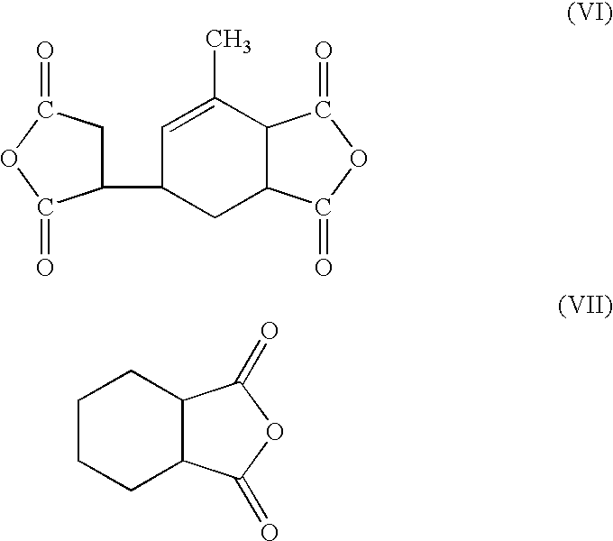
[0048] The following procedure was used to make Sample 1 shown in Table 1. Into a small jar was placed 11.4 grams Z6018, (phenyl propyl hydroxy silicone from Dow Chemicals), 7.5 grams hexahydro-phthalic-anhydride (HHPA) (Ciba Geigy) and 0.4 grams SF1488 (polydimethylsiloxane surfactant from General Electric Co.). A cap was placed onto the jar and the contents heated using a microwave oven to a temperature of approximately 80.degree. C. and mixed until all components were completely dissolved. After dissolution was complete, the sample was cooled to below 50.degree. C., and 15 grams CY179, (cycloaliphatic epoxy resin from Ciba Geigy), 0.1 grams Irganox 1010 (antioxidant from Ciba) and 0.3 grams Tin ethyl-hexanoate were added. The material was blended and filtered through a nominal 5 micron pore sized filter into a clean jar. After filtration, the epoxy blend was degassed by placing it in a vacuum oven set at less than 60.degree. C. for approximately 30 minutes while vacuum was applie...


PUM

PropertyMeasurementUnit
Percent by massaaaaaaaaaa

Abstract

Epoxy resin compositions are disclosed which comprise (A) at least one silicone resin, (B) at least one epoxy resin, (C) at least one anhydride curing agent, (D) at least one siloxane surfactant, and (E) at least one ancillary curing catalyst. Also disclosed are a packaged solid state devices comprising a package, a chip, and an encapsulant comprising a composition of the invention. A method of encapsulating a solid state device is also provided.

Description

[0001] This invention relates to epoxy resin compositions and solid state devices encapsulated therewith. The invention also relates to a method for encapsulating a solid state device.[0002] Solid state devices, sometimes referred to as semiconductor devices or opto-electronic devices, comprise light emitting diodes (LEDs), charge coupled devices (CCDs), large scale integrations (LSIs), photodiodes, vertical cavity surface emitting lasers (VCSELs), phototransistors, photocouplers, opto-electronic couplers and the like. Such devices often exhibit special packaging needs. High-efficiency, high lumen, solid-state white LEDs require a novel packaging material which can withstand more demanding conditions than those required by typical low-intensity, longer wavelength LEDs. Common packaging materials will often undergo a gradual loss of optical and mechanical properties due to the combination of thermal, oxidative and photodegradation processes.[0003] There is thus a continuing need for ...

Claims


Application Information

Patent Timeline
IPC IPC(8): C08G59/42C08G59/58C08K5/5419C08L63/00C08L83/05H01L23/29H01L23/31H01L33/56
CPCC08G59/4284H01L2224/48091C08G77/12C08G77/16C08G77/18C08G77/20C08G77/70C08L63/00C08L83/04H01L33/56C08G77/045H01L2924/3025H01L2924/15747H01L2224/48247C08L83/00C08L2666/14H01L2924/00014H01L2924/00H01L2924/181Y10T428/31663Y10T428/31511H01L2924/00012
Inventor GORCZYCA, THOMAS BERT
Owner GENERAL ELECTRIC CO
Learn More