Resin molded product production process, metal structure production process, and resin molded product

Inactive Publication Date: 2004-09-30
KURARAY CO LTD
View PDF6 Cites 25 Cited by
  • Summary
  • Abstract
  • Description
  • Claims
  • Application Information

AI Technical Summary

Problems solved by technology

This change in values leads to increases in medical care costs and in the number of those who are in between healthy and diseased.
The microarray method generally uses a fluorescence intensity method for detection, and it is unable to obtain accurate gene expression data if detection sensitivity and reproducibility are low.
However, since there is a limit to the enlargable size of a plane substrate, it is unable to obtain given detection sensitivity and reproducibility without decreasing the array density on the substrate.
However, when producing a metal mold by molding, a limit to the mold accuracy imposes restrictions to a pattern of the metal mold.
When producing the metal mold by machining, on the other hand, there is a limit to a cutting tool and cutting accuracy.
Consequently, if the conventional resin molded product is used in the clinical laboratory field, particularly for blood testing, urine testing, biochemical analysis and so on, there is a limit to the accuracy and miniaturization of channels and reservoirs, thus requiring a large amount of sample such as blood.
Further, when using the resin molded product produced by molding or machining, it is unable to provide portability to examination and diagnosis systems.
If the resin molded product formed from the metal mold produced by molding or machining is used in combinatorial chemistry applications, particularly for the high throughput screening in the pharmaceutical development, there is a limit to the miniaturization of reservoirs, which makes it unable to accelerate new drug development and reduce sample requirements for cost reduction.
Similarly, if the above resin molded product is used in combinatorial chemistry applications, particularly for chemical synthesis and analysis in the chemical industry, the limit to the accuracy and miniaturization of channels makes it unable to reduce the time for chemical synthesis and analysis, reduce the amount of drug used for mixture and reaction, reduce the amount of waste solution, and reduce environmental burdens.
Similarly, if the resin molded product produced using the metal mold by molding or machining is used in genetic applications, particularly for analysis by capillary electrophoresis and microarray, and amplification by PCR, the limit to the miniaturization makes it unable to increase the analyzing speed and reduce the sample requir

Method used


Image

  • Resin molded product production process, metal structure production process, and resin molded product
  • Resin molded product production process, metal structure production process, and resin molded product
  • Resin molded product production process, metal structure production process, and resin molded product

Examples


embodiment 1

cl Embodiment 1

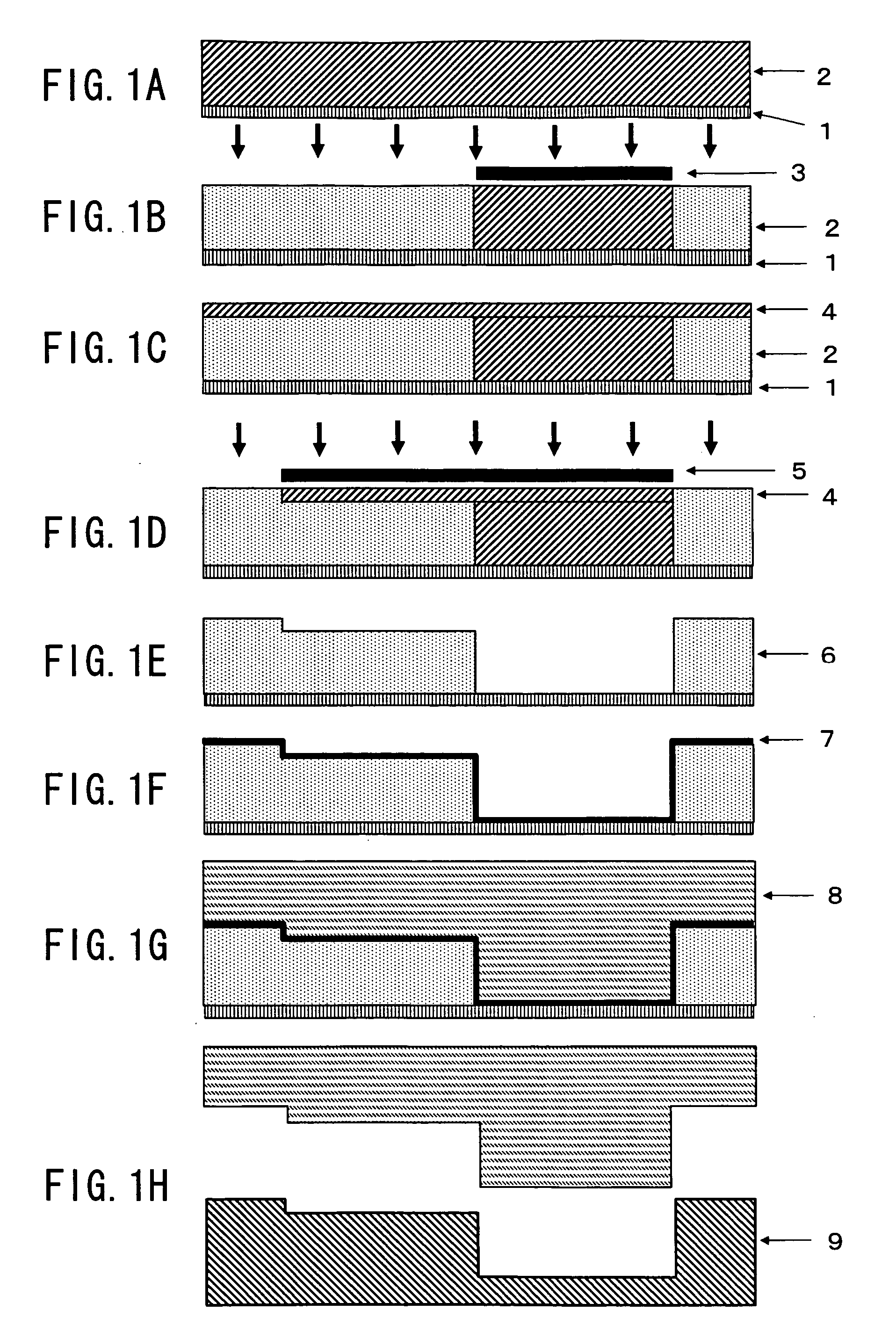
[0087] Referring first to FIG. 1A to 1H, the production process of a resin molded product according to an embodiment of the present invention is shown. This embodiment uses known production equipment, and its detailed explanation is omitted.

[0088] A production process according to this embodiment will be explained hereinafter with reference to FIG. 1A to 1H. FIG. 1A to 1H show a case that uses chemical amplification negative resist. This embodiment forms a resist pattern by the following steps:

[0089] (i) Formation of the first resist layer on a substrate (FIG. 1A)

[0090] (ii) Positioning of the substrate and a mask A (FIG. 1B)

[0091] (iii) Exposure of the first resist layer, with the mask A (FIG. 1B)

[0092] (iv) Heat treatment of the first resist layer (FIG. 1B)

[0093] (v) Formation of the second resist layer on the first resist layer (FIG. 1C)

[0094] (vi) Positioning of the substrate and the mask B (FIG. 1D)

[0095] (vii) Exposure of the second resist layer, with the mask B...

example 1

Production of a Molded Product Having a Channel

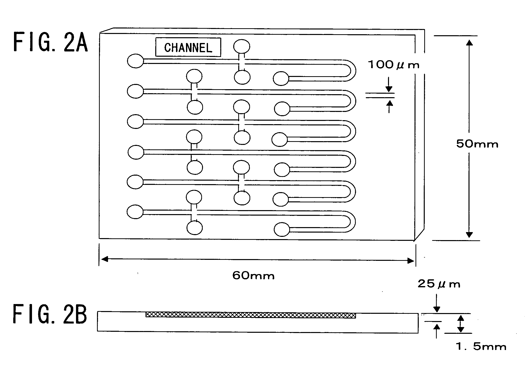
[0163] According to the molded product production process shown in FIG. 1A to 1H, resist coating was repeated two times to form the first resist layer and then exposure and heat-treatment were performed thereon. Further, the resist coating was performed once again to form the second resist layer, and then the exposure and the heat-treatment were performed thereon. A resin molded product, as shown in FIGS. 3A and 3B, having a substrate with 75 mm in width, 50 mm in length, and 1.5 mm in thickness on which a channel with 50 .mu.m and 200 .mu.m in heights was created was thereby produced.

example 2

Production of a Molded Product Having a Channel

[0164] According to the molded product production process shown in FIG. 1A to 1H, resist coating was repeated three times to form the first resist layer and then exposure and heat-treatment were performed thereon. Further, the resist coating was performed once again to form the second resist layer, and then the exposure and the heat-treatment were performed thereon. A resin molded product, as shown in FIGS. 4A and 4B, having a substrate with 75 mm in width, 50 mm in length, and 1.5 mm in thickness on which a channel with 25 .mu.m and 300 .mu.m in heights was created was thereby produced.


PUM

PropertyMeasurementUnit
Solubility (mass)aaaaaaaaaa
Heightaaaaaaaaaa

Abstract

A resin molded product production process has a resist pattern formation step including formation of the first resist layer on s substrate, positioning of the substrate and a mask A, exposure of the first resist layer using the mask A, heat-treatment of the first resist layer, formation of the second resist layer on the first resist layer, positioning of the substrate and a mask B, exposure of the second resist layer using the mask B, heat-treatment of the second resist layer, and development of the resist layers, thereby creating a given resist pattern. The production process further has a metal structure formation step of depositing a metal on the substrate in accordance with the resist pattern by plating, and a molded product formation step of forming a resin molded product by using the metal structure as a mold. A resin molded product is thereby produced.

Description

[0001] 1. Field of the Invention[0002] The present invention relates to a process for producing a resin molded product having a given pattern height or different pattern heights, a resin molded product produced thereby, and a process for producing a metal structure used for the production of a resin molded product. The process according to the present invention is particularly effective in producing a resin molded product used for diagnosis, reaction, separation, measurement, and so on in the clinical laboratory field, the genetic is engineering field, and the combinatorial chemistry field, or a resin molded product used for a channel member for a fuel cell.[0003] 2. Related Background Art[0004] As societies mature, values on medical care and health have changed. People now seek a healthy and high-quality life, not merely a primary health care. This change in values leads to increases in medical care costs and in the number of those who are in between healthy and diseased. With this...

Claims


Application Information

Patent Timeline
IPC IPC(8): B29C33/42B29C33/38B29C45/00B29C45/26B29C67/00C25D1/10G03F7/00G03F7/095G03F7/26
CPCB29C45/00B29C45/26B29C2045/0094G03F7/095B29L2031/756G03F7/0017G03F7/0035B29L2031/753G03F7/00
Inventor NISHI, TAIJIKITANI, TAKENORIYANAGAWA, YUKIHIROFUKUDA, MOTOHIRONAGAYAMA, REI
Owner KURARAY CO LTD
Why Eureka
Try Eureka