Manufacturing method of thin film device substrate

a manufacturing method and thin film technology, applied in the direction of semiconductor devices, electrical devices, transistors, etc., can solve the problems of hindering the diffusion of heat generated by tft operation, and achieve the effects of preventing abnormal operations caused by overheating of thin film devices, improving mechanical strength of thin film device substrates, and low thermal conductivity

Active Publication Date: 2005-05-05
INNOLUX CORP
View PDF1 Cites 12 Cited by
  • Summary
  • Abstract
  • Description
  • Claims
  • Application Information

AI Technical Summary

Benefits of technology

[0031] In effect, the present inventors found out that the aforementioned first problem can be solved if, after forming a TFT in which a polycrystalline film of large grain size obtained through the use of a low-thermal-conductivity film is used as an active layer, this TFT is transferred onto another substrate and the low-thermal-conductivity film is removed, and, thus, reached the present invention. Further, the present inventors found out that the aforementioned second problem can be overcome by the substrate transfer method, wherein, after a structure with a gap space, for instance, a porous silicon oxide film is formed on a substrate and a TFT is formed on that substrate and another substrate is bonded onto that substrate, the structure with a gap space or an overlying layer or an underlying layer of that structure with a gap space is peeled off either by making an etchant penetrate thereto or by breaking mechanically, and, thus, reached the present invention. Moreover, both of the above requirements, that is, a low-thermal-conductivity film and a structure with a gap space can be met by one and the same film such as a porous silicon oxide film and, in this way, the first problem and the second problem can be solved simultaneously.
[0032] In a manufacturing method according to the present invention, after a heat-insulating film and a semiconductor film are successively formed on a first substrate, and laser annealing is applied onto this semiconductor film, and then a second substrate is bonded onto the semiconductor film, the first substrate and the heat-insulating film are peeled off from a layered structure of these films, whereby the heat insulating film is removed altogether so that abnormal operations caused by overheat of the thin film device can be well prevented. Further, even in the case that the heat insulating film is fragile, as the heat insulating film is removed, mechanical strength of the thin film device substrate can be certainly improved.
[0033] Further, when, on a substrate, a primary film is formed and, on the primary film, for example, a semiconductor film is formed and, then, in the semiconductor film, a large number of through holes are formed so as to reach the primary film, and an etchant is supplied from these through holes, a gap space can be formed even under the semiconductor film, and a heat insulating film with an extremely low thermal conductivity can be provided. In this case, if an etchant is supplied for a gap space to remove the heat insulating film in the step of peeling off a first substrate, the surface area of the heat insulating film which comes into contact with the etchant is so large that the first substrate and the heat insulating film can be peeled off with considerable ease. Therefore, no trench fabrication is required to be applied onto the first substrate surface, and a first substrate made of a material which is impervious to light can be used, and besides the first substrate can be peeled off in a short period of time.
[0034] Further, when a peeling-off film is formed over or under the heat-insulating film and peeling-off of the first substrate is made by removing this peeling-off film, no trench fabrication is required to be applied onto the substrate surface, and a material which is impervious to light can be used, and besides the substrate can be peeled off in a short period of time. In this instance, the use of a film having gap spaces as the heat insulating film and accomplishment of rapid penetration of the etchant through the gap spaces can shorten the period of time necessary to remove the peeling-off film.
[0035] Further, if the layered structure between the first substrate and the second substrate is divided into a plural number before the first substrate is peeled off, the distance from the periphery to the center, seen from above, in each divided layered structure becomes shorter so that the time period necessary to peel off can be reduced.
[0036] In other words, in a TFT wherein a polycrystalline film of large grain size obtained through the use of a low-thermal-conductivity film is used as an active layer, the present invention can raise the diffusion rate for the heat generated at the time of operation to transfer from the TFT to the substrate. Further, the problems in the substrate transfer method that the glass substrate surface becomes rough and that a glass substrate impervious to the laser light cannot be used as a substrate can be readily overcome.

Problems solved by technology

Nevertheless, with the conventional techniques, the heat insulating film is left lying thereunder so that the heat insulating film hinders diffusion of the heat the TFT operation generates.
In short, the very heat insulating film that is useful at the time of laser annealing becomes the primary cause of the abnormal operation at the time of the thin film device operation.

Method used


Image

  • Manufacturing method of thin film device substrate
  • Manufacturing method of thin film device substrate
  • Manufacturing method of thin film device substrate

Examples


first example

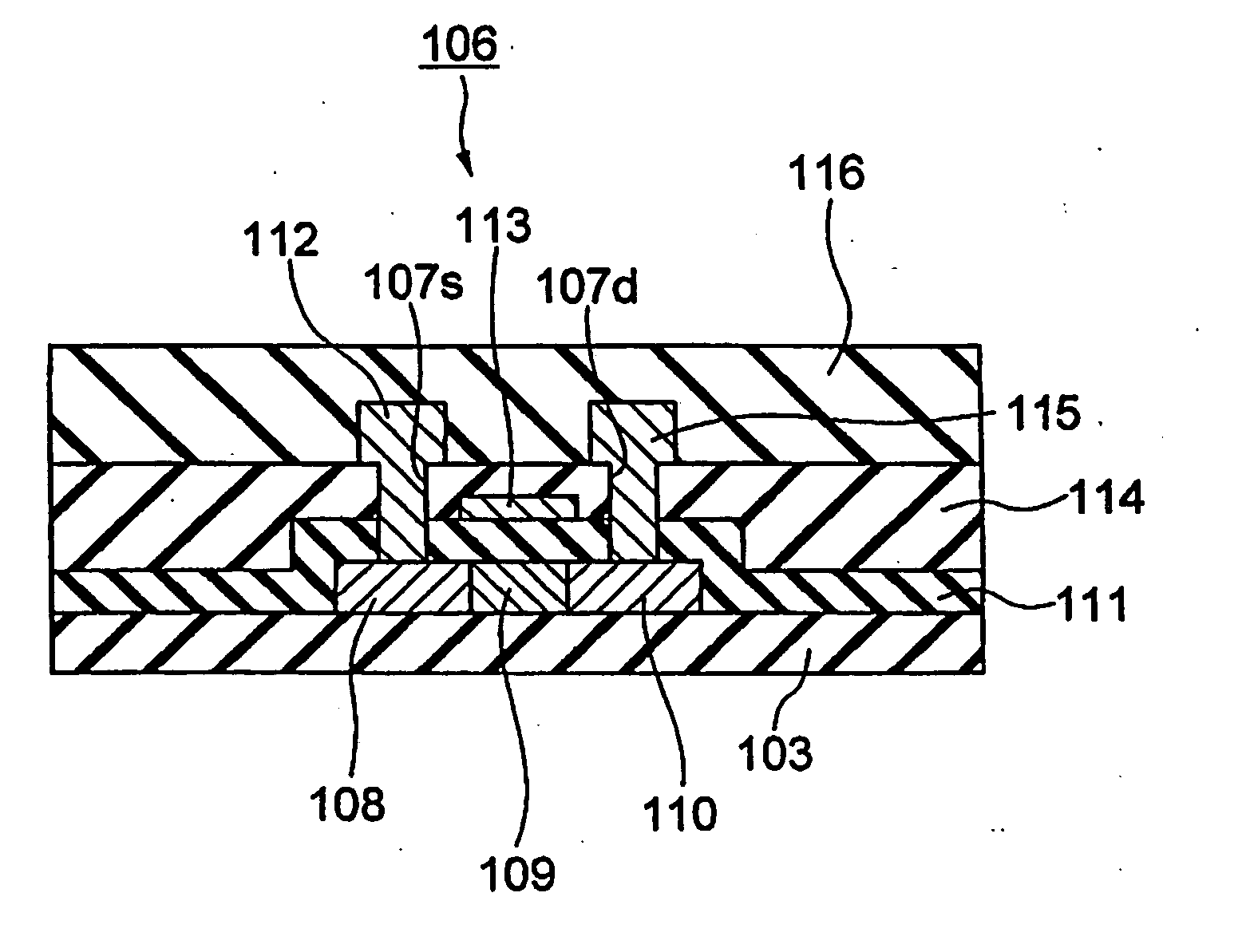
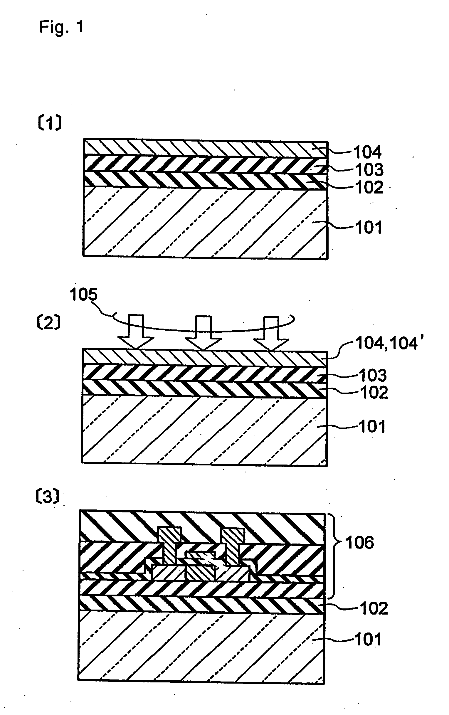
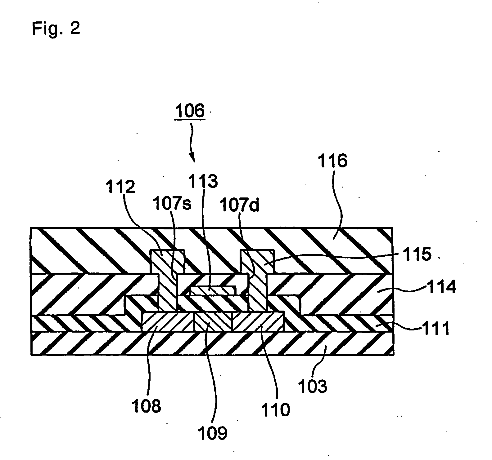
[0073]FIGS. 4 and 5 are a series of schematic cross-sectional views illustrating Example 1 of the present invention. The steps of a manufacturing method thereof proceed in the order of FIG. 4(1), FIG. 4(2), FIG. 4(3), FIG. 4(4), FIG. 5(1), FIG. 5(2) and FIG. 5(3). Referring to these drawings, the embodiment of the present invention is described below.

[0074] Firstly, as shown in FIG. 4(1), on a glass substrate 301, a porous silicon oxide film 302 is formed by the spin coating method as a heat insulating film, and on the porous silicon oxide film 302 a silicon oxide film 303 is formed, and then an amorphous silicon oxide film 304 is formed by the LPCVD (Low Pressure Chemical Vapor Deposition) method. A liquid used in this spin coating method is, for example, a solution of silanol-based monomers or oligomers dissolved in an organic solvent such as alcohol or ketone or a solution in which fine powders of silicon oxide are dispersed and suspended in an organic solvent. By dropping the l...

second example

[0078]FIGS. 6 and 7 are a series of schematic cross-sectional views illustrating Example 2 of the present invention. The steps of a manufacturing method thereof proceed in the order of FIG. 6(1), FIG. 6(2), FIG. 6(3), FIG. 6(4), FIG. 7(1), FIG. 7(2) and FIG. 7(3). Referring to these drawings, the embodiment of the present invention is described below.

[0079] As shown in FIG. 6(1), on a glass substrate 401, a chromium film 401′ is first formed as a peeling-off film, for example, by the sputtering method, and on the chromium film 401′ a porous silicon oxide film 402 is formed as a heat insulating film by the spin coating method, and, then, on the porous silicon oxide film 402 a silicon oxide film 403 is formed by the plasma CVD method, and thereon an amorphous silicon film 404 is further formed by the thermal CVD method. Following that, as shown in FIG. 6(2), the amorphous silicon film 404 is irradiated from above with a laser beam 405 of an excimer laser to obtain a polycrystalline s...

third example

[0082]FIGS. 8-17 are sets of schematic views illustrating Example 3 of the present invention, each set showing a plan view and one or two cross-sectional views. The steps of a manufacturing method thereof proceeds in the order of FIG. 8, FIG. 9, FIG. 10, FIG. 11, FIG. 12, FIG. 13, FIG. 14, FIG. 15, FIG. 16 and FIG. 17. Referring to these drawings, the embodiment of the present invention is described below.

[0083] Firstly, as shown in FIG. 8, on a glass substrate 501, a silicon oxide film 502, a silicon nitride film 503 and an amorphous silicon oxide film 504 are successively formed in this order. The silicon nitride film 503 is formed by the PECVD (Plasma-Enhanced CVD) method. In this instance, hydrogen is fed into the CV chamber as a source gas, whereby a silicon nitride film containing a considerable amount of hydrogen is formed. In this way, the etching rate of silicon nitride by hydrofluoric acid can be made very small in comparison with that of silicon oxide.

[0084] Next, as sh...


PUM

PropertyMeasurementUnit
temperatureaaaaaaaaaa
heataaaaaaaaaa
heat insulatingaaaaaaaaaa

Abstract

An object of the present invention is to prevent the thin film device formed by laser annealing from making, due to overheat, abnormal operations. Firstly, on a glass substrate 101. a heat insulating film, a silicon oxide film and an amorphous silicon film are formed in succession, and the amorphous silicon film is irradiated from above with a laser beam of an excimer laser. After being molten, the amorphous silicon film undergoes recrystallization to form a polycrystalline silicon film. Subsequently, using the polycrystalline silicon film as an active layer, a TFT is formed, and then a plastic substrate is bonded onto the TFT, and finally the glass substrate is peeled off by way of the heat insulating film, whereby a transfer of the TFT is completed. Because the heat insulating film is removed, abnormality caused by overheat at the time of operation is well prevented from occurring.

Description

BACKGROUND OF THE INVENTION [0001] 1. Field of the Invention [0002] The present invention relates to a manufacturing method of a thin film device substrate which comprises the step of transferring a thin film device formed on one substrate onto another substrate. [0003] 2. Description of the Related Arts [0004] For the switching element in the pixel section of the liquid crystal display unit, the thin film transistor (referred to as the “TFT” hereinafter) has been being widely used. In recent years, with the object of achieving the liquid crystal display unit of higher precision as well as producing the system on glass (referred to as the “SOG” hereinafter) successfully, there have been growing demands for higher operation speeds. The SOG herein is a technique to integrate, along with the TFT for driving the liquid crystal, the TFTs in adjacent circuits such as the driver circuit, the memory and the CPU (Central Processing Unit) onto one glass substrate. (First Conventional Techniq...

Claims


Application Information

Patent Timeline
Patent Type & Authority Applications(United States)
IPC IPC(8): H01L21/02H01L21/336H01L21/20H01L21/77H01L21/84H01L27/12H01L29/786
CPCH01L27/1214H01L27/1266H01L29/66757H01L2221/68368H01L2221/68359H01L2221/68363H01L2221/6835
Inventor NAKATA, MITSURUTAKECHI, KAZUSHIGEKANOH, HIROSHI
Owner INNOLUX CORP
Why Eureka
Try Eureka