Structure and method for contact pads having a recessed bondable metal plug over of copper-metallized integrated circuits

a technology of integrated circuits and contact pads, which is applied in the direction of semiconductor devices, semiconductor/solid-state device details, electrical apparatus, etc., can solve the problems significant technological challenges, and the relative high resistivity of interconnecting aluminum now appears inferior to the lower resistivity of metals such as copper, so as to reduce the risk of aluminum smearing or scratching and electrical shorting, and facilitate the shrinking of the pitch of the contact pads

Inactive Publication Date: 2005-09-22
TEXAS INSTR INC
View PDF4 Cites 12 Cited by
  • Summary
  • Abstract
  • Description
  • Claims
  • Application Information

AI Technical Summary

Benefits of technology

[0010] Embodiments of the present invention are related to wire-bonded IC assemblies, semiconductor device packages, surface mount and chip-scale packages. It is a technical advantage that the invention offers a low-cost method of reducing the risk of aluminum-smearing or -scratching and electrical shorting between contact pads. The assembly yield of high input/output

Problems solved by technology

Consequently, the relatively high resistivity of the interconnecting aluminum now appears inferior to the lower resistivity of metals such as copper.
Further, the pronounced sensitivity of aluminum to electromigration is becoming a serious obstacle.
From the standpoint of the mature aluminum interconnection technology, however, this shift to copper is a significant technological challenge.
For bond pads made of copper, the formation of thin copper(I)oxide films during the manufacturing process flow has to be prevented, since these films severely inhibit reliable attachment of bonding wires, especially for conventional gold-wire ball bonding.
In contrast to aluminum oxide films overlying metallic aluminum, copper oxide films overlying metallic copper cannot easily be broken by a combination of thermocompression and ultrasonic energy appli

Method used


Image

  • Structure and method for contact pads having a recessed bondable metal plug over of copper-metallized integrated circuits
  • Structure and method for contact pads having a recessed bondable metal plug over of copper-metallized integrated circuits
  • Structure and method for contact pads having a recessed bondable metal plug over of copper-metallized integrated circuits

Examples


Embodiment Construction

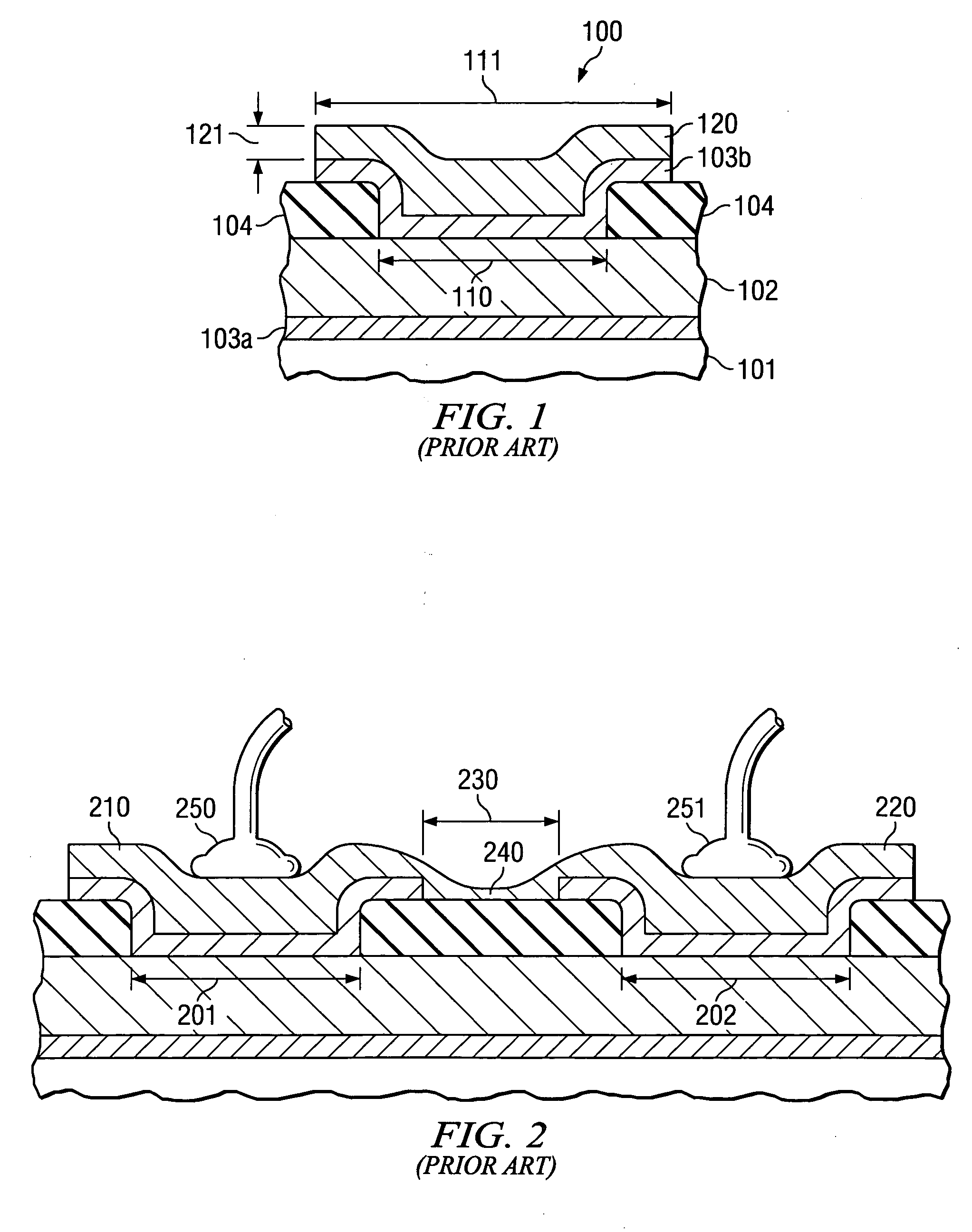
[0017] The technical advantages offered by the invention can be best appreciated by comparing an embodiment of the invention with the conventional method of wire-bonding a contact pad of an integrated circuit (IC) chip, which uses copper as interconnecting metal. An example of a conventional structure is depicted in FIG. 1. In the schematic cross section of an IC contact pad generally designated 100, 101 is an intra-level dielectric, which may consist of silicon dioxide, a low-k dielectric, or any other suitable insulator customarily used in ICs. 102 represents the top level IC copper metallization (thickness typically between 200 and 500 nm, contained by barrier layers 103a and 103b (typically tantalum nitride, typically 10 to 30 nm thick) from diffusing into other IC materials. In the essentially moisture-impermeable overcoat layer 104 (typically between 500 to 1000 nm of silicon nitride, silicon oxynitride, or silicon dioxide, single-layered or multi-layered) is contact window 11...


PUM


Abstract

A metal structure for an integrated circuit, which has copper interconnecting metallization (311) protected by an overcoat layer (320). A portion of the metallization is exposed in a window (301) opened through the thickness of the overcoat layer. The metal structure comprises a patterned conductive barrier layer (330) positioned on the copper metallization, wherein this barrier layer forms a trough with walls (331) conformal with the overcoat window. The height (331a) of the wall is less (between 3 and 20%) than the overcoat thickness (320a), forming a step (340). A plug (350) of bondable metal, preferably aluminum, is positioned in the trough and has a thickness equal to the trough wall height (331a).

Description

FIELD OF THE INVENTION [0001] The present invention is related in general to the field of electronic systems and semiconductor devices and more specifically to bond pad structures and fabrication methods of copper metallized integrated circuits. DESCRIPTION OF THE RELATED ART [0002] In integrated circuits (IC) technology, pure or doped aluminum has been the metallization of choice for interconnection and bond pads for more than four decades. Main advantages of aluminum include easy of deposition and patterning. Further, the technology of bonding wires made of gold, copper, or aluminum to the aluminum bond pads has been developed to a high level of automation, miniaturization, and reliability. [0003] In the continuing trend to miniaturize the ICs, the RC time constant of the interconnection between active circuit elements increasingly dominates the achievable IC speed-power product. Consequently, the relatively high resistivity of the interconnecting aluminum now appears inferior to ...

Claims


Application Information

Patent Timeline
IPC IPC(8): H01L21/44H01L21/60H01L21/768H01L23/485H01L23/52
CPCH01L21/7684H01L2224/0401H01L24/05H01L24/11H01L24/45H01L24/48H01L2224/04042H01L2224/05073H01L2224/05147H01L2224/05166H01L2224/05181H01L2224/05184H01L2224/05187H01L2224/05624H01L2224/13099H01L2224/45144H01L2224/48091H01L2224/48463H01L2224/48624H01L2224/85201H01L2924/01005H01L2924/01006H01L2924/01013H01L2924/01014H01L2924/01022H01L2924/01028H01L2924/01029H01L2924/01042H01L2924/01073H01L2924/01074H01L2924/01075H01L2924/01079H01L2924/01327H01L2924/04953H01L2924/05042H01L2924/14H01L2924/3025H01L24/03H01L2224/05556H01L2924/01033H01L2924/01024H01L2924/01023H01L2924/01019H01L2924/00014H01L2924/04941H01L2924/181H01L2924/00
Inventor LI, LEIHORTALEZA, EDGARDO R.
Owner TEXAS INSTR INC
Why Eureka
Try Eureka