Dehydroxylation and purification of calcium fluoride materials using a halogen containing plasma

a technology of halogen containing plasma and calcium fluoride, which is applied in the direction of polycrystalline material growth, chemistry apparatus and processes, crystal growth process, etc., can solve the problems of low economic manufacturability, affecting the and reducing the burden on the demands for improved performance of computers and other electronic devices

Inactive Publication Date: 2005-12-01
CORNING INC
View PDF7 Cites 7 Cited by
  • Summary
  • Abstract
  • Description
  • Claims
  • Application Information

AI Technical Summary

Problems solved by technology

The burden of the demands for improved performance of computers and other electronic devices falls on the lithographic processes used to fabricate integrated circuit chips.
However, the commercial use and adoption of below 200 nm wavelengths has been hindered by the transmission nature of such deep ultraviolet wavelengths through optical materials and by the lack of economically manufacturable, high quality blanks of optically transmissive materials suitable for below 200 nm microlithography optical elements.
Commercially available raw material powders are sufficiently pure in terms of cationic impurities, but these materials are not sufficiently pure in terms of the anionic impurities they contain.
While the use of an oxygen scavenger during the crystal growth process can alleviate the oxygen contamination problem, such use can give rise to additional problems.
This is frequently difficult to determine.
While the use of excess scavenger does not present problems when the scavenger is gaseous, when a solid scavenger such as PbF2 is used, the excess of scavenger could result in lead contamination of the grown crystal.
If insufficient scavenger is used, then residual oxygen containing substances may be present in the grown crystal and these substances will absorb radiation in the 120-220 nm regions, and consequently interfere with the transmission properties of the crystal and optical element made from it.

Method used


Image

  • Dehydroxylation and purification of calcium fluoride materials using a halogen containing plasma
  • Dehydroxylation and purification of calcium fluoride materials using a halogen containing plasma
  • Dehydroxylation and purification of calcium fluoride materials using a halogen containing plasma

Examples


example 1

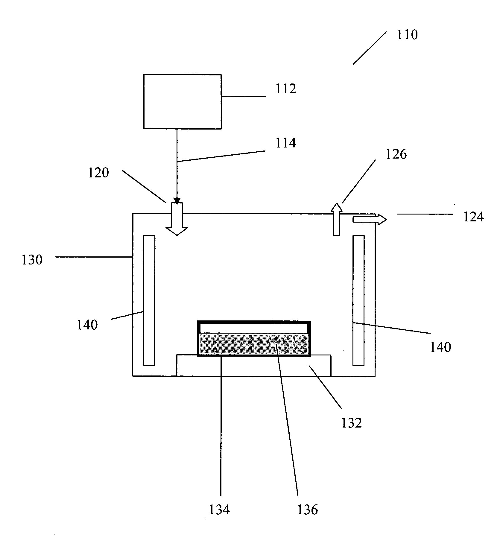
[0052] Referring to FIG. 1, the Figure illustrates a system 110 for treating a metal fluoride raw material having a plasma generator 112 having a source of a halogen or halogen-containing gas (not illustrated) and an exit port 116 (not illustrated) with connector 114 for transfer of the plasma formed by generator 112 to a furnace 130. The furnace 130 has a inlet port 120 for receiving the plasma, an outlet port 126, a port 124 for applying vacuum, heaters 140, a support 132 for one or a plurality of crucibles 134 (broad black lines, one crucible illustrated) or other vessel containing a metal fluoride powder 136, and other accessories such as temperature and pressure controllers, temperature probes or thermocouples that are not illustrated. The crucible 134 containing the metal fluoride material is placed on the support stand 132 and the furnace is evacuated to a pressure of less than 10−3 mm Hg to outgas the fluoride material, and in particular to remove oxygen and any easily remov...

example 2

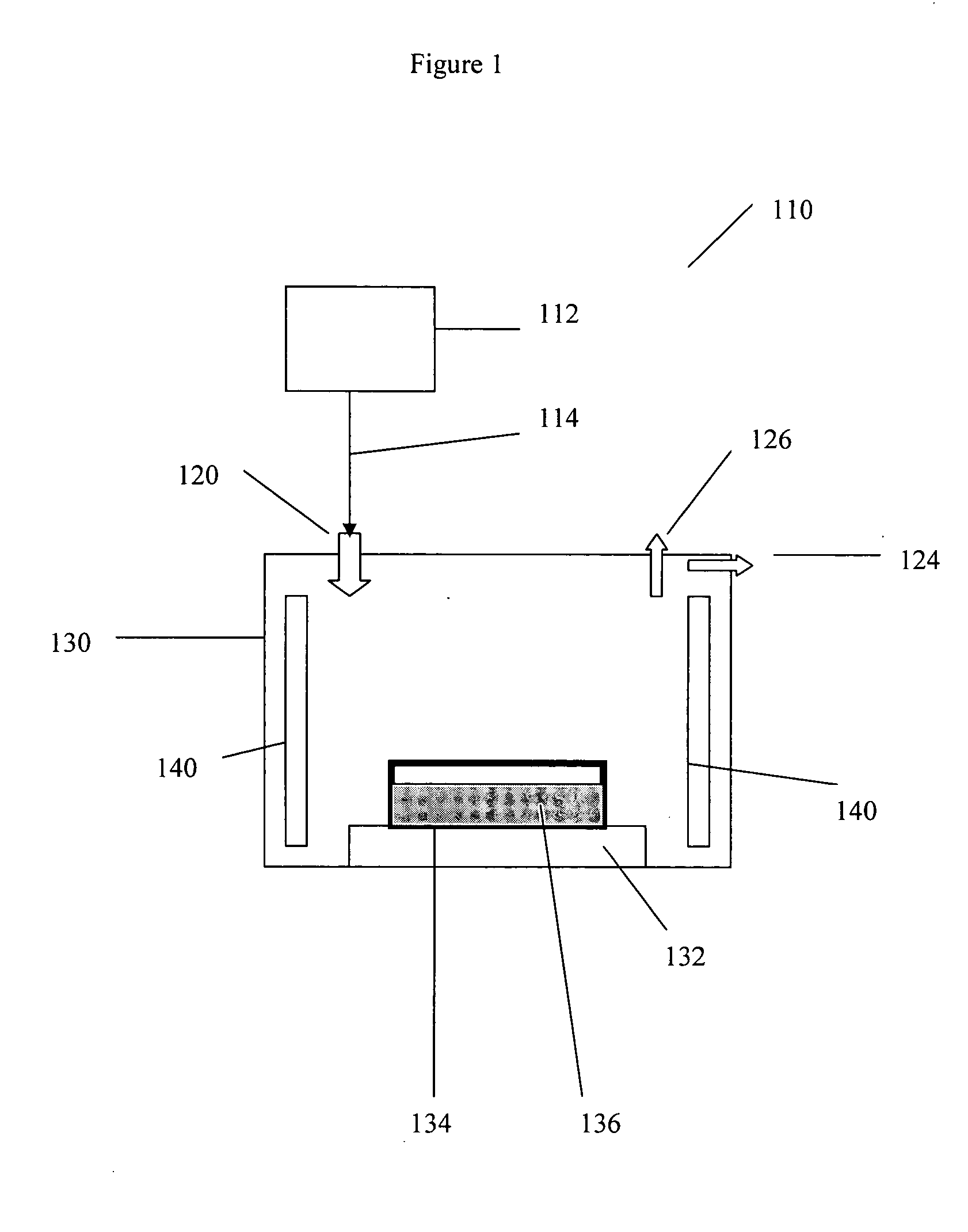
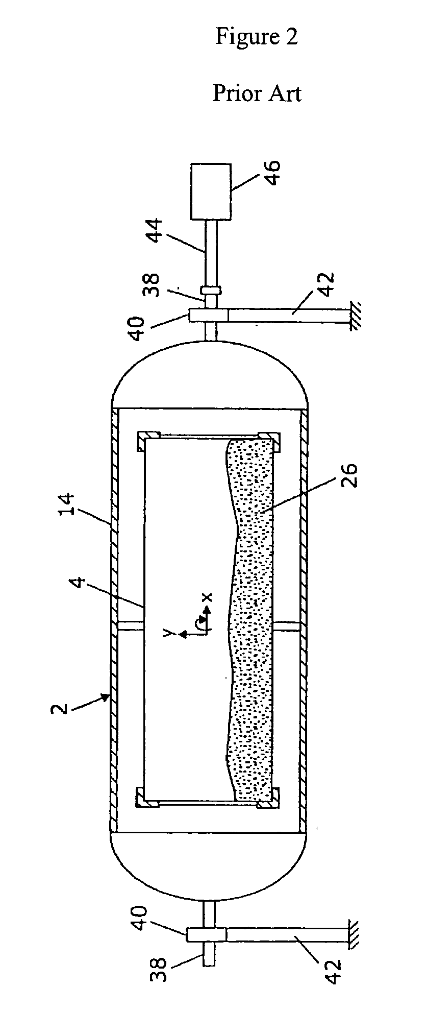
[0056] In this Example one uses a rotating vessel as illustrated in FIG. 2 which has been disclosed in U.S. Patent Application Publication 2003 / 0070606, published Apr. 17, 2003 and commonly owned along with the present application by Corning Incorporated to prepare a metal fluoride raw material for use in growing single crystals. As used in the present invention, the reaction vessel 14 has shaft ends 38 supported by bearings 40. The bearing 40 are attached to support frames 42. One side of the shafts 38 is coupled to a drive shaft 44 that is connected to a drive system 46, e.g., drive motor and gear train. The drive system 46 can be operated to rotate both the reaction vessel 14 and the reaction chamber 4. Rotary / flexible couplings (not shown) can be used to couple inlet port 16 to plasma 32 or a gas 20 source and to couple outlet port 18 to a treatment chamber 22 for treating substances exiting the vessel. During treatment with a halogen containing plasma the reaction chamber 4 is ...

example 3

[0058]FIGS. 3A and 3B illustrate in a simplified manner an embodiment of the invention in which a crucible containing a metal fluoride raw material is placed in a crystals growth furnace, treated with plasma and then used to grow a metal fluoride single crystal. This use of this procedure avoids the re-contaminating the plasma-treated metal fluoride material during transfer from a treatment furnace to a growth furnace.

[0059] In FIG. 3A a plasma generator 440 is connected to furnace 400 via connector 442. Furnace 400 has heaters 410 and 411 that can be controlled that are separately controlled, baffles 412 that divide the furnace into two upper and lower zones, element 450 connected to the furnace via a connector for the application of vacuum, and element 452 that is connected to the furnace for the admission of selected gases, for example, inert gases such as nitrogen, helium and argon; fluorinating gases such as CF4, F2, XeF2, C2F4Cl2, cyclo-C4F8 and other fluorinating gases known...


PUM

PropertyMeasurementUnit
pressureaaaaaaaaaa
temperatureaaaaaaaaaa
pressureaaaaaaaaaa

Abstract

The invention is directed to a process of purifying metal fluoride materials used to make metal fluoride single crystals suitable for making optical elements used in the transmission of wavelengths below 200 nm, and in particular to a process of purifying such materials by the use of a halogen containing plasma to convert metal oxygenates contaminating the feedstocks used in the preparation of the crystals to metal fluorides. The invention also is directed to a process of growing a metal fluoride single crystal using a crystal growth furnace to carry out the foregoing purification procedure followed by the steps of melting the purified material and cooling it using s selected time and temperature cycle to from a metal fluoride single crystal. The plasmas used in practicing the invention can be derived from a variety of halogenated materials including, for example, fluorocarbons, chlorocarbons, boron trihalides, chlorine, fluorine, xenon difluoride and other gaseous or easily volatilized halogenated substances known in the art.

Description

FIELD OF THE INVENTION [0001] The invention is directed to a process of purifying metal fluoride materials used to make metal fluoride single crystals suitable for making optical elements used in the transmission of wavelengths below 200 nm, and in particular to a process of purifying such materials by the use of a halogen containing plasma to convert metal oxygenates contaminating the feedstocks used in the preparation of the crystals to metal fluorides. BACKGROUND OF THE INVENTION [0002] The burden of the demands for improved performance of computers and other electronic devices falls on the lithographic processes used to fabricate integrated circuit chips. Lithography involves irradiating a mask and focusing the pattern of this mask through an optical microlithography system onto a wafer coated with a photoresist. The pattern on the mask is thereby transferred onto the wafer. Decreasing the line-widths of the features on a given wafer enables the writing on a wafer of more elemen...

Claims


Application Information

Patent Timeline
Patent Type & Authority Applications(United States)
IPC IPC(8): C01B9/08C01F11/22C30B1/00C30B9/00C30B11/00C30B17/00C30B28/06C30B29/12
CPCC01B9/08C30B29/12C30B11/00C01F11/22
Inventor BELLMAN, ROBERT A.BOOKBINDER, DANA C.GADKAREE, KISHOR P.GIROUX, CYNTHIA B.
Owner CORNING INC
Why Eureka
Try Eureka