Method for producing hologram by pico-second laser

a micro-hologram and laser technology, applied in the field of micro-hologram production, can solve the problems of difficult recording of embedded holograms, distortion of pulsed laser beam waveforms, etc., and achieve the effects of reducing waveform distortion, stably recording, and significantly reducing the generation of harmonics from air or non-linear optical crystals

Inactive Publication Date: 2006-01-26
JAPAN SCI & TECH CORP
View PDF4 Cites 28 Cited by
  • Summary
  • Abstract
  • Description
  • Claims
  • Application Information

AI Technical Summary

Benefits of technology

[0022] Further, the energy peak value of the laser pulses is provided by Et / τ, and the influence of the optical non-linear interaction, or deformation in the waveform of the laser pulse during propagation, is reduced as the energy peak value is lowered. Thus, if the laser pulse width is increased from the level of femtoseconds to the level of 10 picoseconds while maintaining the entire laser energy Et at a constant value, a hologram can be stably recorded. Further, in case of recording a hologram embedded in a material, the pulsed laser beams should be propagated through the material. Thus, the effective energy Ef at a value equal to or greater than the threshold value, and by encoding the pulse width τ up to about 10 picoseconds, which reduces the distortion of the waveform due to the propagation through the material by setting an embedded hologram can be encoded in a depth of 10 μm or more from the surface of the distortion of the waveform due to the propagation through the material by setting material.
[0023] In the picosecond pulses, the generation of harmonics from air or non-linear optical crystals is significantly reduced due to the lowered peak energy of the leaser pulses, and thereby it is difficult to achieve the spatial and temporal matching between the two pulsed laser beams based on the above principle. Thus, femtosecond laser beams having a high peak energy are first used to achieve spatial and temporal matching therebetween, and then the laser pulse width τ is expanded keeping the optical configuration unchanged through a process of relaxing the phase matching of a laser light based on chirping. In this manner, the temporal and spatial matching can be maintained even between the picosecond pulses to allow an embedded hologram to be recorded. In case where a diffraction grating is written in an optical fiber or an optical waveguide, it is required to write the diffraction grating in a core region on the inside of a cladding layer at an embedding depth of 10 μm to 2 mm. In the method of the present invention, the embedding depth can be freely controlled by the converged spots to eliminate any restriction on the embedding depth.

Problems solved by technology

As mentioned above, the conventional process of recording a pure irreversible hologram in a non-photosensitive material using interfering femtosecond laser pulses involves a problem concerning the distortion in the waveforms of pulsed laser beams due to a non-linear optical interaction between the femtosecond laser pulses and air / the material.
Such instability makes it very difficult to record an embedded hologram.

Method used


Image

  • Method for producing hologram by pico-second laser
  • Method for producing hologram by pico-second laser
  • Method for producing hologram by pico-second laser

Examples


example 1

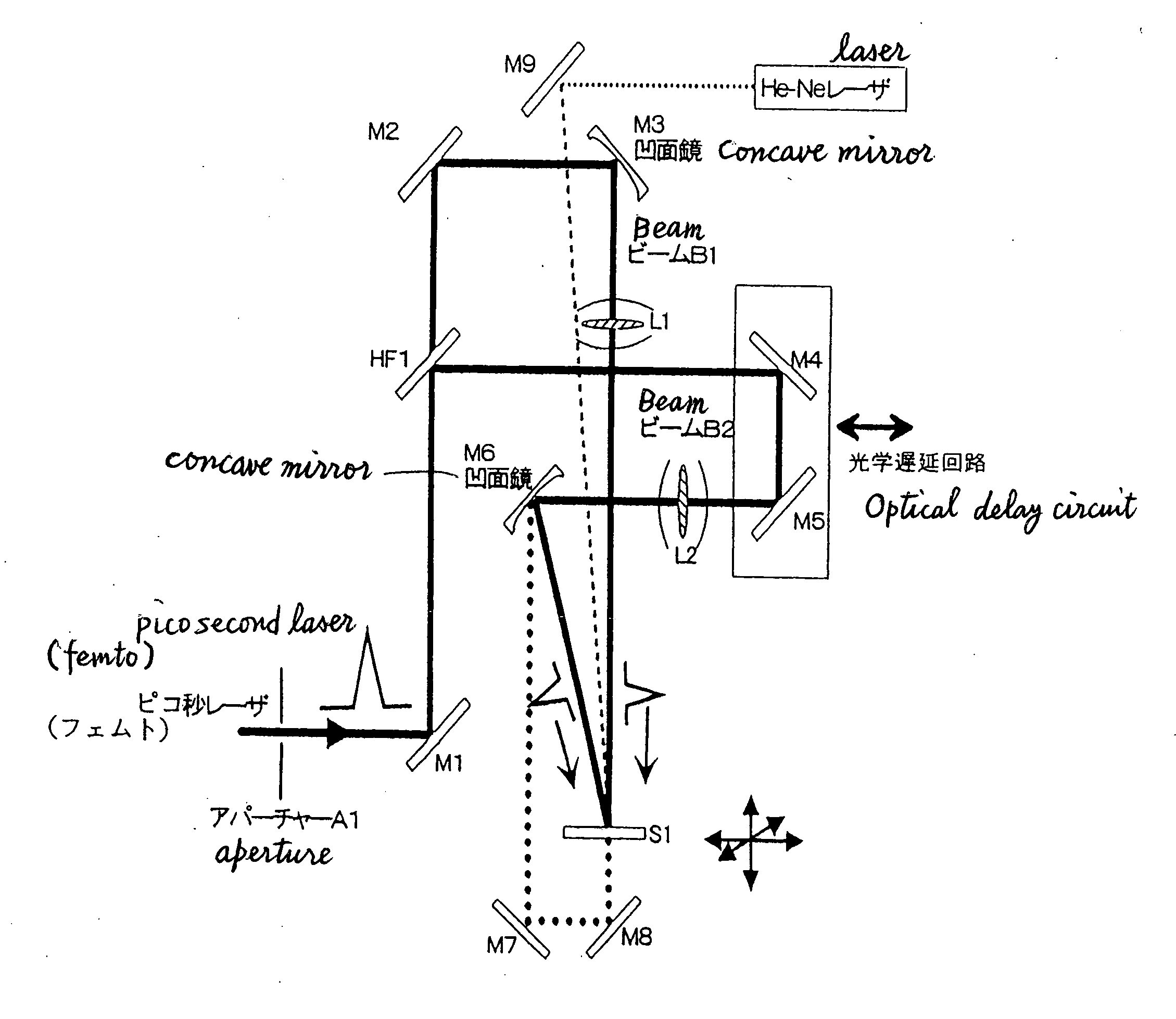
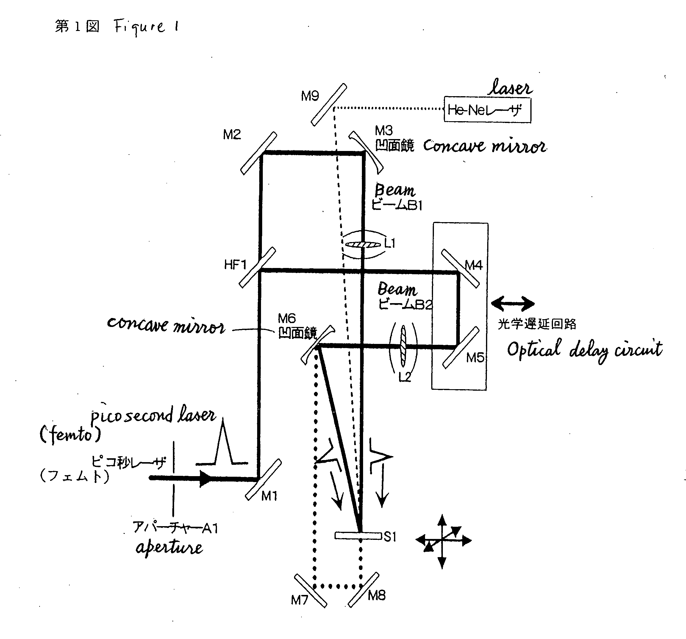
[0046] The two-beam laser interfering exposure apparatus illustrated in FIG. 1 was used. That is, a laser was the regenerative-amplifier titanium-sapphire laser for generating a pulsed laser light with an oscillation center frequency of about 800 nm, a pulse width τ of about 100 femtoseconds, and a pulse energy of 50 μJ / pulse for each of the two beams.

[0047] The pulsed laser light was divided into two beams by the half mirror HF1, and converged by the lens L1 and the lens L2. An optical delay circuit and an optical-path positioning circuit were interposed in one of the optical paths for the beam B1 and the beam B2, and the converged spots of the two beams were matched with one another temporally and spatially according to the intensity of a third harmonic generation wave induced by air. The size of the matched spot was about 100 μm, and the peak density was calculated as about 1 J / cm2 . The incident angle of the beams B1 and B2 at the workpiece S1 was set at 45-degree.

[0048] Then,...

example 2

[0051] The two-beam laser interfering exposure apparatus illustrated in FIG. 1 was used. That is, a laser was the regenerative-amplifier titanium-sapphire laser for generating a pulsed laser light with an oscillation center frequency of about 800 nm, a pulse width τ of about 100 femtoseconds, and a pulse energy of 50 μJ / pulse for each of the two beams. The pulsed laser light was divided into two beams by the half mirror HF1, and converged by the lens L1 and the lens L2. An optical delay circuit and an optical-path positioning circuit were interposed in one of the optical paths for the beam B1 and the beam B2, and the converged spots of the two beams were matched with one another temporally and spatially according to the intensity of the third harmonic generation wave induced by air.

[0052] The size of the matched spot was about 100 μm, and the peak density was calculated as about 1 J / cm2. The incident angle of the beams B1 and B2 at the workpiece was set at 45-degree. Then, a pulse-...

example 3

[0054] The two-beam laser interfering exposure apparatus illustrated in FIG. 1 was used. That is, a laser was the regenerative-amplifier titanium-sapphire laser for generating a pulsed laser light with an oscillation center frequency of about 800 nm, a pulse width τ of about 100 femtoseconds, and a pulse energy of 50 μJ / pulse for each of the two beams.

[0055] The pulsed laser light was divided into two beams by the half mirror HF1, and converged by the lens L1 and the lens L2. An optical delay circuit and an optical-path positioning circuit were interposed in one of the optical paths for the beam B1 and the beam B2, and the converged spots of the two beams were matched with one another temporally and spatially according to the intensity of the third harmonic generation wave induced by air. The size of the matched spot was about 100 μm, and the peak density was calculated as about 1 J / cm2.

[0056] The incident angle of the beams B1 and B2 at the workpiece was set at 45-degree. Then, a...


PUM


Abstract

Disclosed is a method of producing a hologram through a two-beam laser interfering exposure process, which comprises emitting a coherent laser light with a pulse width (τ) ranging from greater than 900 femtoseconds to 100 picoseconds and a laser power of 10 μJ/pulse or more using a solid-state laser as a light source, dividing the pulses light from the laser into two beams, controlling the two beams temporally and spatially in such a manner that the two beam are converged on a surface of or inside a workpiece for recording a hologram while matching the respective converged spots of the two beams with one another temporally and spatially to create the interference therebetween so as to record a surface-relief hologram on the surface of the workpiece or an embedded hologram inside the workpiece in an irreversible manner. The present invention can solve a problem with a conventional process of recording a hologram in a non-photosensitive material in an irreversible manner using interfering femtosecond laser pulses, specifically, distortion in the waveforms of pulsed laser beams and resulting instability in recording of an embedded hologram due to a non-linear optical interaction between the femtosecond laser pulses and air/the material.

Description

TECHNICAL FIELD [0001] The present invention relates to a method of producing a micro-hologram in a transparent compound, semiconductor, organic material or metal, using interfering laser pulses with high energy density, and a hologram produced through the method. BACKGROUND ART [0002] A method of preparing holographic optical elements or diffraction grating elements by utilizing the interference between leaser beams is one of well-known techniques commonly used for years. The diffraction gratings produced by the interfering laser exposure are applied to various devices, such as spectrometer, distributed feedback semiconductor lasers or fiber grating devices. The laser for use in the production process of such diffraction gratings includes a He—Cd laser, an argon ion laser, an excimer laser, a continuous wave laser or a nanosecond pulsed laser. These lasers can emit a beam with a relatively low energy density, and thereby a material to be processed is required to have photosensitivi...

Claims


Application Information

Patent Timeline
Patent Type & Authority Applications(United States)
IPC IPC(8): G03H1/04G02B5/18G02B5/32G03H1/26
CPCG02B5/1857G03H2270/52G03H1/0244G03H1/04G03H2001/0413G03H2001/0415G03H2001/0482G03H2001/0484G03H2001/0491G03H2222/33G03H2223/26G03H2240/24G03H2260/62G03H2270/13G02B17/023
Inventor HOSONO, HIDEOHIRANO, MASAHIROKAWAMURA, KENICHIMIURA, TAISUKEKAMIOKA, HAYATO
Owner JAPAN SCI & TECH CORP
Why Eureka
Try Eureka