High efficiency balanced detection interferometer

a detection interferometer and high-efficiency technology, applied in the field of optical imaging, can solve the problems of reducing the optical efficiency of the interferometer, and wasting virtually 75% of the optical power supplied by the light source in this configuration, and achieving the effect of reducing the cost of the system

Inactive Publication Date: 2006-05-25
CARL ZEISS MEDITEC INC
View PDF22 Cites 38 Cited by
  • Summary
  • Abstract
  • Description
  • Claims
  • Application Information

AI Technical Summary

Benefits of technology

[0013] In configuration Aii, the post fiber coupler is also made unbalanced and a single detector is used. By properly controlling the optical power split ratio of both the prior fiber coupler and the post fiber coupler, a theor...

Problems solved by technology

However, this configuration is limited to an optical efficiency of 25% as explained below.
Otherwise, the signal will be degraded by the optical power noise of the source.
Hence virtually 75% of the optical power supplied by the light source is wasted in this configuration.
Another issue with the classic Michelson interferometer (FIG. 1) is that light from the reference arm is coupled back into the optical source, causing side effects that can impact the quality of the resulting image.
However, due to the fact that a practical fast-scanning optical delay line operates in reflection mode, a second circulator is needed, and this will increase the cost of the system.
However, in the case of Ai and Aii, although the SNR is maximized, if a retroreflective ODL is desired in these c...

Method used


Image

  • High efficiency balanced detection interferometer
  • High efficiency balanced detection interferometer
  • High efficiency balanced detection interferometer

Examples


embodiment 1

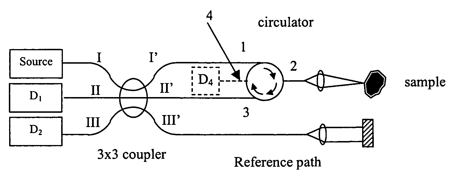
[0041]FIG. 3a shows a first embodiment of the present invention. The light source introduces to the system a light wave. The light source can be any tunable, narrowband, or broadband light source having a center wavelength within the optical spectrum range from ultra-violet to near infrared. It is preferably derived from a laser, a tunable laser, a superluminescent diode (SLD), a light emitting diode (LED), a short pulsed laser such as a Ti:sapphire laser, a photonic crystal fiber laser or a spontaneous emission based rare earth doped optical fiber broad band light source. The light source is coupled to an input port (port I) of a monolithic 3×3 fiber coupler. A 3×3 coupler has a first set of three ports and a second set of three ports, and has the property that some light entering any port in first set is coupled to each port in the second set. For example a fused junction between three fibers is an example of a 3×3 coupler. It is preferred but not absolutely required that the 3×3 ...

embodiment 2

[0053]FIG. 4 shows another embodiment, in which two 2×2 couplers are connected in cascade. A 2×2 coupler has a first pair of ports and a second pair of ports, and has the property that some light entering any port in first set is coupled to each port in the second set. For example a fused junction between two fibers is an example of a 2×2 coupler. Another example of a 2×2 coupler is a plate beam-splitter. The net effect of this configuration is similar to that of embodiment 1. We will not repeat similar descriptions but rather highlight the differences. The key differences include the following: the first 2×2 coupler directly connected to the source is preferably an uneven split ratio coupler that channels most of the light to the sample path wherein light returned from the sample is channeled via the circulator to another 2×2 coupler that has a 50 / 50 split ratio; while the 50 / 50 coupler ensures that the interfered light waves in the two arms leading to detectors D1 and D2 are 180 d...

embodiments 3 and 4

[0059] As can be seen from embodiment 1 and embodiment 2, in order to ensure a dual balanced detection, strictly speaking, the split ratio of the recombining coupler for the returned sample wave and reference wave must be kept at 50 / 50 and there should be most preferably no more attenuation to either of the two interfered waves. In the case of embodiment 1, due to the fact that there is a small amount of recombined light being coupled at the coupling region back to the source arm, the phase relationship between the two interfered light waves propagating to detector D1 and detector D2 is not exactly 180 degrees out of phase but only close to this value. In the case of embodiment 2, although the relative phase relationship of the two light waves propagating to detector D1 and detector D2 is exactly 180 degrees out of phase for the case of a perfect 50 / 50 recombining coupler, the interfered light wave propagating to detector D1 is attenuated more than that propagating to detector D2. D...


PUM


Abstract

An interferometer configured for use in optical coherence domain (OCT) reflectometry systems is disclosed. In the preferred embodiments, efficient routing of light and a balanced detection arrangement provide a high signal to noise ratio. In a first set of embodiments, a 3×3 coupler is used to split light along separate sample and reference paths and also for combining light returning from those paths and supplying the interfered collected light to the detection system. In an alternate set of embodiments, a pair of cascaded 2×2 couplers provides a similar function. The interferometer can be used with various OCT modalities including time-domain and frequency domain approaches.

Description

PRIORITY CLAIM PROVISIONAL [0001] This patent application claims priority to U.S. Provisional Patent Application No. 60 / 629,429, filed Nov. 19, 2004, which is incorporated herein by reference.BACKGROUND OF THE INVENTION [0002] 1. Field of the Invention [0003] The invention relates generally to optical imaging using optical coherence tomography and in particular to systems and methods for achieving balanced detection with high signal to noise ratio. [0004] 2. Description of Related Art [0005] Optical coherence domain reflectometry (OCDR) is a technique initially developed to provide a higher resolution over optical time domain reflectometry (OTDR) for the characterization of the position and the magnitude of reflection sites in such optical assemblies as optical fiber based systems, miniature optical components and integrated optics (Youngquist et al., “Optical Coherence-Domain Reflectometry: A New Optical Evaluation Technique”, 1987, Optics Letters 12(3):158-160). With the addition ...

Claims


Application Information

Patent Timeline
IPC IPC(8): G01B9/02
CPCG01B9/02G01B9/02091G01B2290/40
Inventor ZHOU, YANEVERETT, MATTHEW J.HACKER, MARTIN
Owner CARL ZEISS MEDITEC INC
Why Eureka
Try Eureka