Manufacturing method of substrate having conductive layer and manufacturing method of semiconductor device

a manufacturing method and technology of a semiconductor device, applied in the direction of semiconductor/solid-state device details, diodes, inductances, etc., can solve the problems of reducing yield, forming short circuits of conductive layers, and reducing yield, so as to achieve uniform width and distance of conductive layers, and uniform thickness of conductive layers

Inactive Publication Date: 2006-06-22
SEMICON ENERGY LAB CO LTD
View PDF4 Cites 60 Cited by
  • Summary
  • Abstract
  • Description
  • Claims
  • Application Information

AI Technical Summary

Benefits of technology

[0023] According to the invention, a low wettability region is formed on the periphery of a region where a conductive layer is formed. Therefore, a conductive paste does not spread in the region, and the peripheral region of the conductive layer can be prevented from having a small taper angle due to overflowing from an opening of a mask. Thus, a uniform thickness of the conductive layer can be achieved. In addition, a uniform line width and distan

Problems solved by technology

When a print with conductive paste is conducted on a substrate by screen printing, however, the conductive paste filling in an opening of a mask spreads from the opening, which causes overflow.
A conductive layer formed by baking such a conductive paste is short-circuited with an adjacent layer, leading to reduced yield.
In the regions 1612 with a narrow line width

Method used


Image

  • Manufacturing method of substrate having conductive layer and manufacturing method of semiconductor device
  • Manufacturing method of substrate having conductive layer and manufacturing method of semiconductor device
  • Manufacturing method of substrate having conductive layer and manufacturing method of semiconductor device

Examples


embodiment mode 1

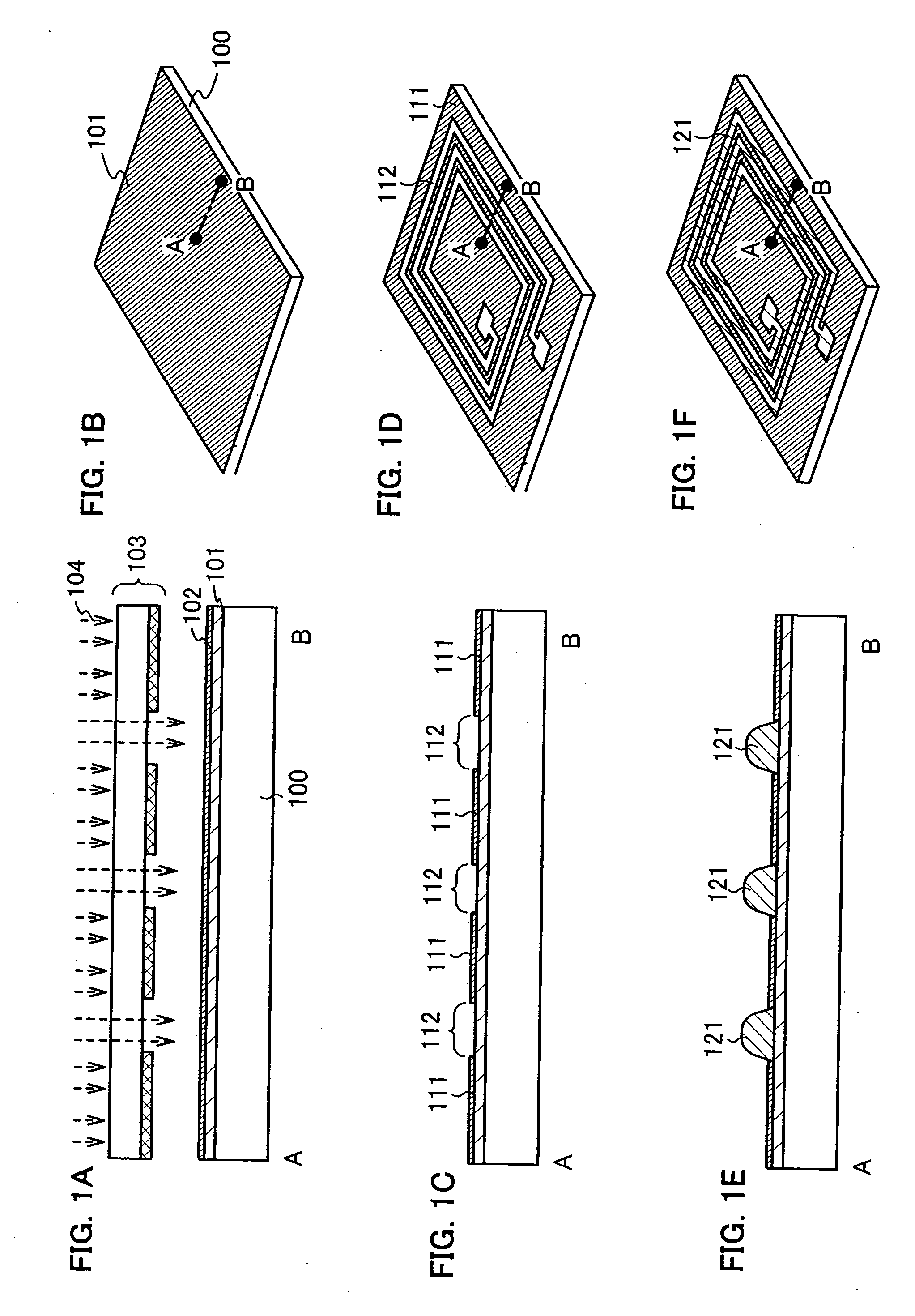
[0042] In this embodiment mode, steps of forming regions with different wettability over a substrate using a photomask, and steps of forming a conductive layer in the high wettability region are described with reference to FIGS. 1A to 1F. In this embodiment mode, description is made using an antenna as a typical example of a conductive layer.

[0043]FIGS. 1B, 1D and 1F are perspective views of a substrate having an antenna, and FIGS. 1A, 1C and 1E are cross sectional views along a line A-B.

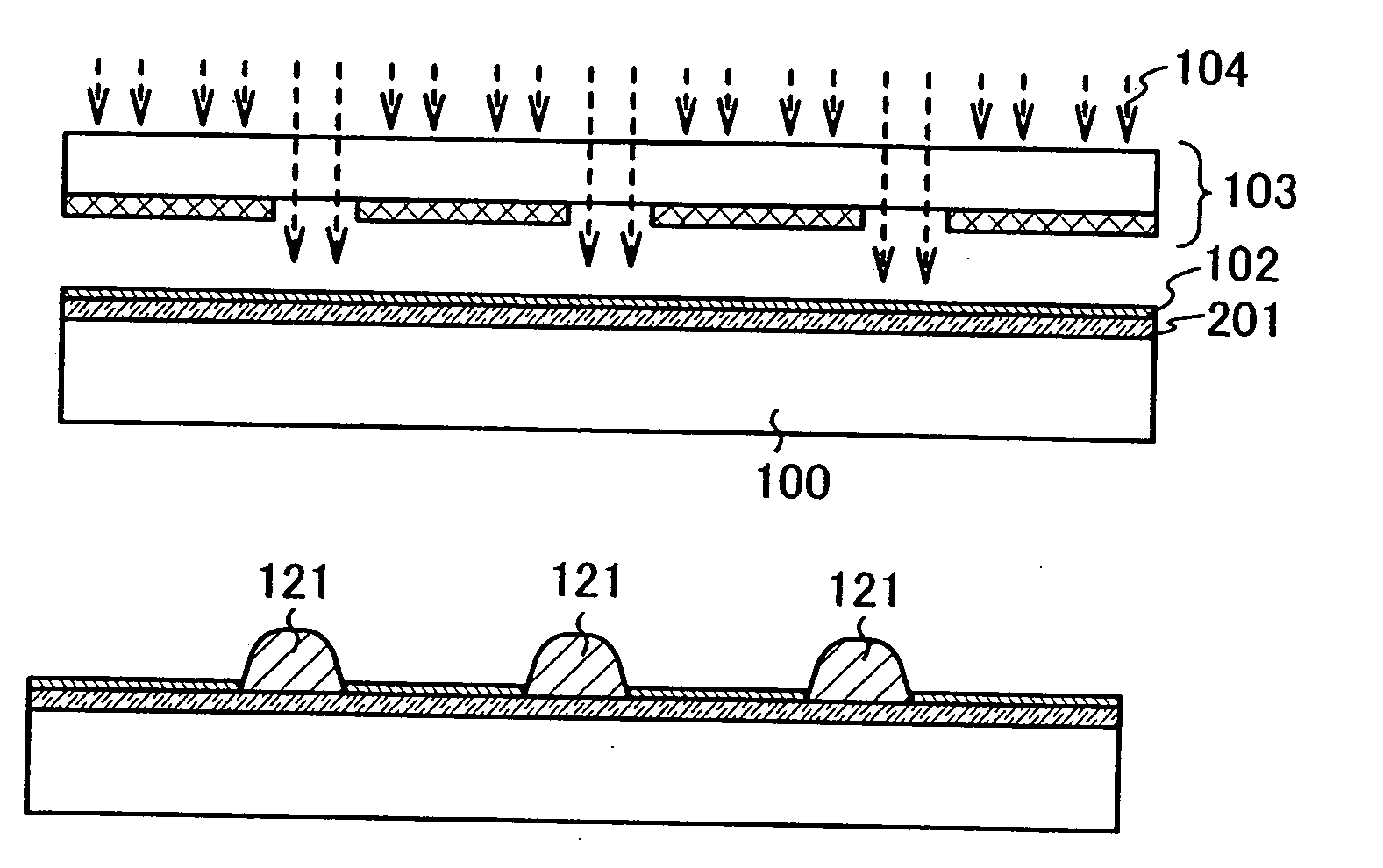
[0044] An inorganic insulating layer 101 is formed over a substrate 100, and a low wettability layer 102 is formed over the inorganic insulating layer 101 (see FIGS. 1A and 1B).

[0045] The substrate 100 may be a glass substrate, a quartz substrate, a substrate made of an insulating substance such as ceramic such as alumina, a plastic substrate, a silicon wafer, a metal plate or the like.

[0046] The plastic substrate is typically made of polyethylene naphthalate (PEN), polypropylene, polypropylene ...

embodiment mode 2

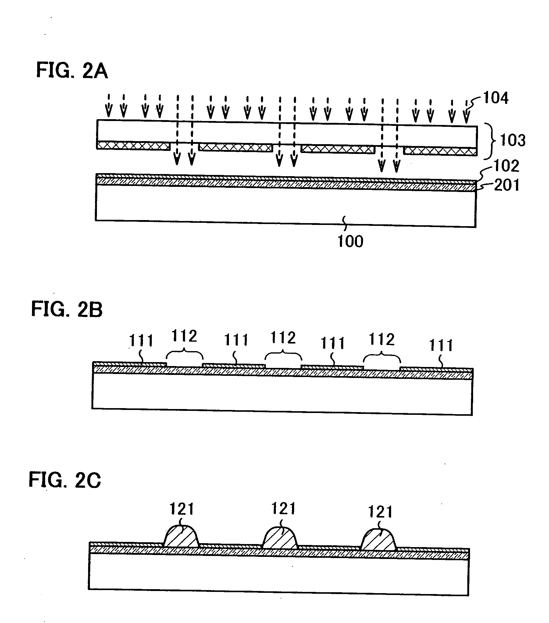
[0073] In this embodiment mode, manufacturing steps of a conductive layer forming region, which are effectively performed compared to Embodiment Mode 1, are described with reference to FIGS. 2A to 2C. In this embodiment mode, a low wettability layer is effectively exposed to light using a photocatalytic layer.

[0074] A photocatalytic layer 201 is formed over the substrate 100, and the low wettability layer 102 is formed over the photocatalytic layer 201 (see FIG. 2A).

[0075] The photocatalytic layer 201 is formed of titanium oxide (TiOx), titanate (MTiO3) such as strontium titanate (SrTiO3), tantalate (MTaO3), niobate (M4Nb6O17), (note that every “M” indicates a metal element), cadmium sulfide (Cds), zinc sulfide (ZnS), cadmium selenide (CdSe), potassium tantalate (KTaO3), zirconium oxide (ZrO2), niobium oxide (Nb2O5), zinc oxide (ZnO), iron oxide (Fe2O3), tungsten oxide (WO3), or the like.

[0076] The photocatalytic layer 201 is formed by sputtering, plasma CVD, vapor deposition, so...

embodiment mode 3

[0083] In this embodiment mode, a low wettability layer is exposed to light without using a photomask.

[0084] The inorganic insulating layer 101 is formed over the substrate 100, and photocatalytic layers 301 each having a desired shape are formed over the inorganic insulating layer 101 (see FIG. 3A). Then, a low wettability layer 302 is formed over the photocatalytic layers 301 and the inorganic insulating layer 101 (see FIG. 3B). In this embodiment mode, the photocatalytic layers 301 have the same shape as conductive layers that are formed later.

[0085] The photocatalytic layers 301 are irradiated with the light 104 to be activated. As a result, the low wettability layer 302 that is in contact with the photocatalytic layers 301 is selectively reacted, and the substance of the low wettability layer is decomposed, thereby forming high wettability regions 304. In this embodiment mode, the photocatalytic layers 301 are exposed in the high wettability regions 304; however, the inventio...


PUM


Abstract

The manufacturing method of a substrate having a conductive layer has the steps of: forming an inorganic insulating layer over a substrate; forming an organic resin layer with a desired shape over the inorganic insulating layer, forming a low wettability layer with respect to a composition containing conductive particles on a first exposed portion of the inorganic insulating layer; removing the organic resin layer; and coating a second exposed portion of the inorganic insulating layer with a composition containing conductive particles and baking, thereby forming a conductive layer.

Description

BACKGROUND OF THE INVENTION [0001] 1. Field of the Invention [0002] The present invention relates to a substrate having a conductive layer such as a wire and an antenna, which is provided in a semiconductor device such as a wireless chip, a wireless tag, a wireless IC, an RFID and an IC tag and used for communicating data bi-directionally and wirelessly, and to a manufacturing method thereof. The invention also relates to a manufacturing method of a semiconductor device having an antenna for communicating data bi-directionally and wirelessly. [0003] 2. Description of the Related Art [0004] In recent years, ICs having a function of communicating data wirelessly have been actively developed, such as a wireless tag, an IC tag and a contactless IC card. The IC tag and the contactless IC card require an antenna for communicating data wirelessly. The antenna is formed by embedding a coil of wire, printing, etching of a conductive thin film, plating or the like. Above all, the printing is ...

Claims


Application Information

Patent Timeline
IPC IPC(8): H01L21/311H01L21/302
CPCH01L23/48H01L23/5227H01L2924/07811H01L27/0629H01L27/12H01L27/1266H01L27/13H01L28/10H01L29/78621H01L2924/12044H01L2924/3011H01L27/1292H01L24/11H01L2924/00H01L2224/0554H01L2224/05568H01L2224/05573H01L2924/00014H01L2924/14H01L2924/15788H01L2224/05599H01L2224/0555H01L2224/0556
Inventor FUJII, GENMORISUE, MASAFUMISHOJI, HIRONOBUMARUYAMA, JUNYADAIRIKI, KOUJIAOKI, TOMOYUKI
Owner SEMICON ENERGY LAB CO LTD
Why Eureka
Try Eureka