Staple and anvil anastomosis system

a staple and anvil technology, applied in the field of intraluminally directed anastomosis methods, systems and procedures, can solve the problems of rising to a potentially lethal colorectal cancer, local lack of oxygen, and inability to implement conventional exploration and anastomosis techniques, etc., to achieve less or no hospitalization time, less medical resources, and less time.

Inactive Publication Date: 2006-07-27
VITAL ACCESS CORP
View PDF99 Cites 46 Cited by
  • Summary
  • Abstract
  • Description
  • Claims
  • Application Information

AI Technical Summary

Benefits of technology

[0080] Additionally, another object of this invention is to provide methods, systems, and apparatuses to enable the performance of minimally invasive anastomoses that do not require the interruption of blood flow in the receiving blood vessel.
[0094] A feature of the catheter assisted endoscopic or peripheral procedure of this invention is the versatility of the intravascular catheter and of the extravascular device for signaling the anastomosis site and cooperatively performing the anastomosis. Accordingly, a variety of devices and techniques can be advantageously combined in the context of this invention to enhance the performance of its methods, systems and apparatuses.

Problems solved by technology

If the colonoscopy had not been performed and any existing polyp had been left attached to the intestinal wall, such polyp might have become a malignant tumor thus giving rise to a perhaps lethal colorectal cancer.
Reduction of blood vessel patency, and in general a disruption in a vessel's blood flow, can lead to ischemia, which is a local lack of oxygen in tissue due to a mechanical obstruction of the blood supply.
Conventional exploration and anastomosis techniques are not always implemented in such a way as to satisfy the demand for an easier, quicker, less damaging, but reliable vascular anastomosis.
Accordingly, the time and resources that are spent during the exploration and diagnostic phases are not directly employed in the performance of an appropriate corrective action, such as an anastomosis.
By performing an anastomosis considerably after the initial exploration has taken place and in a different location and clinical environment, these conventional procedures also waste a significant part of the information acquired at the exploration phase.
This process sacrifices potentially useful information.
Fluoroscopic visualization is no longer available without repeating the angiogram procedure, and in conventional practice external anatomic localization is used in correlation with previously recorded images.
However, having to reacquire information leads to a waste of resources, it significantly increases the period of time from exploration to corrective action, it is an additional burden on the patient, and it enhances the invasive character of the treatment that is administered to the patient.
Regarding the application of sutures in vascular anastomoses, it has been generally reported that “the insertion of transmural stitches, even in experienced hands that employ atraumatic techniques and fine sutures, causes significant damage to the vessel wall.
In addition to proximal occlusion, needle-and-suture-mediated intimal penetration is believed to represent a source of platelet emboli, which can cause distal embolization and thus a hazard in brain revascularization and myocardial circulation.
Furthermore, it is considered that “suture anastomosis of small vessels is time-consuming and tedious and demands a long and continuous training if high patency rates are to be regularly achieved.” Willy D. Boeckx, Oliskevigius Darius, Bert van den hof, and Carlo van Holder, Scanning Electron Microscopic Analysis of the Stapled Microvascular Anastomosis in the Rabbit, Annals of Thoracic Surgery, Vol. 63 (1997) p. S128.
Furthermore, the 180° eversion of vessel ends is viewed as an operation that can be difficult, particularly in sclerotic vessels.
Nevertheless, clipping may lead to irregularities at the junction of the anastomosed vessels.
In addition, it has been reported that “both periadventitial tissue stripping and microvascular clip application have deleterious effects in the early postoperative period” and that “temporary clips with a lesser width must be used in place of microvascular clips” while performing microvascular anastomosis. S. Keskil, N.
Although a number of coupling techniques do not place any foreign body in the intraluminal space of the anastomosed vessels, it is considered that the use of a foreign rigid body such as a ring that encloses a dynamically dilating structure is a disadvantage of this type of technique.
Furthermore, this type of technique is viewed as not being flexible enough for its application to significant vessel size discrepancies in end-to-side anastomosis, and the devices are characterized as being of limited availability and needed in sets of different sizes.
In addition, most coupling techniques require considerable eversion, incisions and mounting of the coupling devices that are difficult or impossible to apply endoscopically.
In contrast, it has been reported that the application of thrombin-based fibrin sealant (fibrin glue) to microvascular anastomoses can have noticeable deleterious effects, particularly when used in venous anastomosis.
Glues used in anastomotic practice face the challenges inherent to factors that include toxicity, thrombogenicity, vascular wall thinning, and mechanical strength of the joint.
Generally, the use of lasers in anastomotic practice faces the challenges inherent to factors that include the cost of laser purchase, maintenance and training, radiation damage to surrounding tissue, aneurism formation, the need for about three or four sutures (versus the nine or ten sutures applied in conventional anastomosis), side effects of heat-induced tissue welding, and mechanical failure at the anastomosis site.
A common feature of most conventional stapling, coupling and clipping techniques, particularly when applied to small-diameter vessels, is that they require a temporary interruption of the blood stream in the recipient vessel, a disruption that is thought to be not very well tolerated in cardiac bypass surgery.
In revascularization procedures of the brain, temporary occlusion of a proximal brain artery may cause brain ischemia, and consequently a nonocclusive anastomosis technique is required.
As the instrumentation that is needed at the anastomosis site becomes complex and cumbersome, a wider open area is needed for accessing the anastomosis site, thus leading to an increasingly invasive procedure.
In addition, techniques that rely on devices that are exposed to the blood flow may lead to technical problems associated with a persistent intraluminal foreign body.

Method used


Image

  • Staple and anvil anastomosis system
  • Staple and anvil anastomosis system
  • Staple and anvil anastomosis system

Examples


example 1

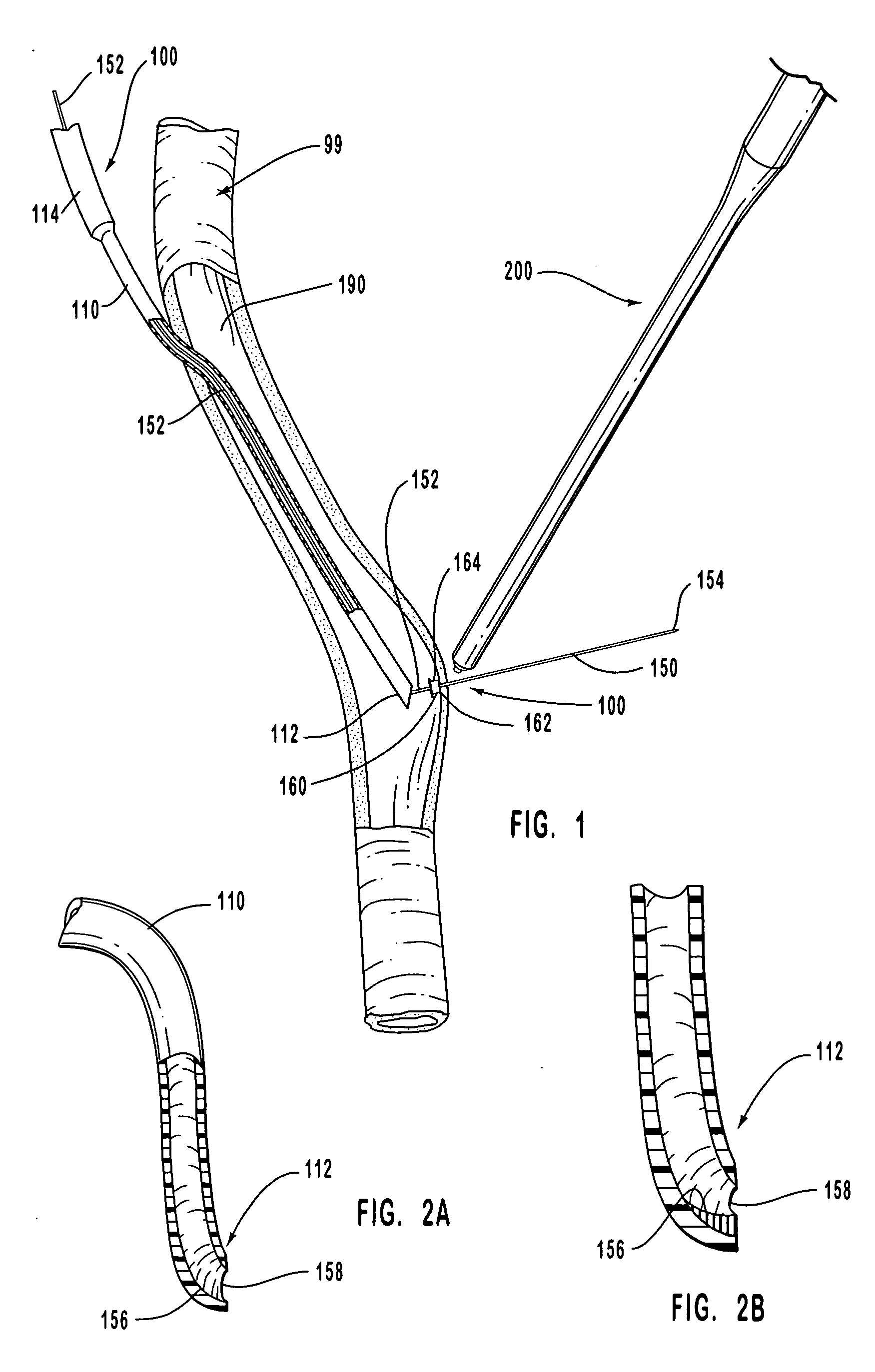
[0235] In common hemodialysis practice, an artery is shunted to a vein with a vessel that channels the blood flow from the artery to the vein. This vessel is anastomosed at one end to the artery and at the other end to the vein, and it is used in hemodialysis for extracting and subsequently injecting the blood that is dialyzed. Embodiment 200A is used for anastomosing the ends of the vessel that provides the artery-to-vein shunt.

[0236] More particularly, only one end or both ends of the graft vessel can be anastomosed with embodiment 200A. When the graft vessel is anastomosed at both of its ends with embodiment 200A, an end of a graft vessel is anastomosed to the receiving blood vessel while the other end is left open, and another graft is similarly anastomosed at a different site of the receiving blood vessel. The open ends are then joined with a sleeve according to standard practice.

example 2

[0237] Embodiment 200B is also used for anastomosing structures to facilitate hemodialysis in similar fashion as disclosed in Example 1 regarding embodiment 200A. Embodiment 200B, however, relies on clips that do not penetrate the walls of the anastomosed structures and consequently are not exposed to the blood flow, a feature that should minimize the risk of clot formation.

example 3

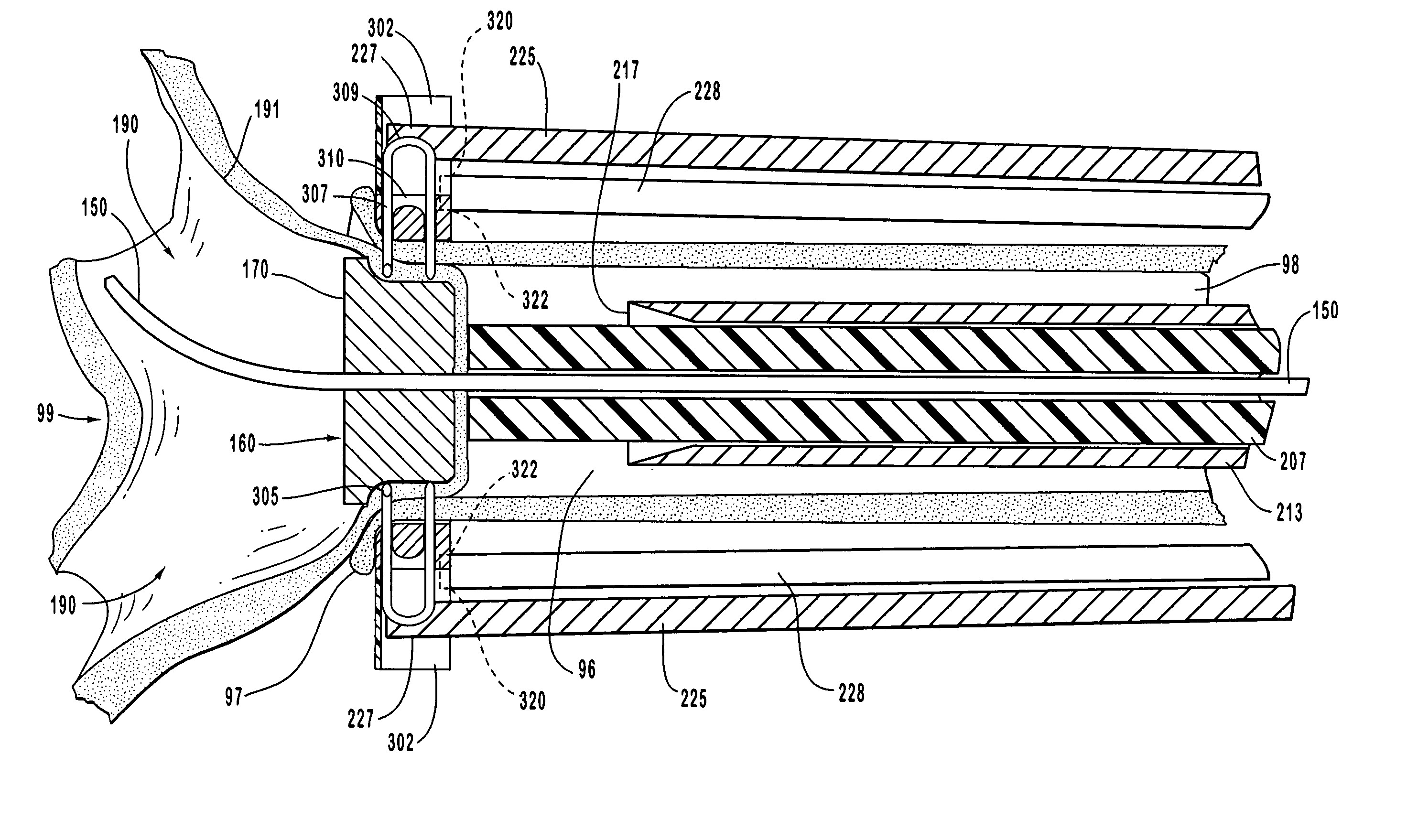
[0238] To describe this exemplary embodiment of anastomosis device 200 of this invention, reference is made to FIGS. 8-14. In this embodiment, staple engaging device 219, activation sheath 233, staple guide ring 300 with staples 308, and anastomosis ring 350 in the embodiments shown in FIGS. 8-14 are replaced by hand suturing or by a suturing device such as the suturing device disclosed for example in U.S. Pat. No. 5,860,992 which has been herein incorporated by reference in its entirety. The anvil of this invention, such as anvil 160, provides an abrasion resistant surface that deflects the sharp end of a suturing needle.

[0239] Suturing is a technique that has been practiced for a long time, and its features and characteristics are fairly well known. When compared to one of the anastomosis devices herein disclosed, however, suturing sometimes requires a more invasive procedure, it requires comparatively more intensive and specialized training, and it does not provide for the stand...


PUM


Abstract

The present invention relates to new and useful apparatus, systems and methods for providing an effective tool for intraluminally directed vascular anastomosis of a graft vessel to a receiving blood vessel that is performed according to a minimally invasive procedure. The intraluminally directed vascular anastomosis does not require the interruption of blood flow in the receiving blood vessel and it is versatile enough to suitably combine a variety of cutting, welding, soldering, sealing, and joining techniques. The intraluminally directed anvil apparatus comprises an anvil and a wire used for signaling the optimal anastomosis site; this signaling can be performed when the initial exploration is performed. An anastomosis device is used in conjunction with the intraluminally directed anvil apparatus for opening the anastomosis fenestra and joining the anastomosed structures.

Description

RELATED APPLICATIONS [0001] This application is a divisional of U.S. patent application Ser. No. 10 / 706,245 titled STAPLE AND ANVIL ANASTOMOSIS SYSTEM, filed Nov. 12, 2003. Ser. No. 10 / 706,245 is a continuation of U.S. patent application Ser. No. 10 / 243,543 titled ANVIL APPARATUS FOR ANASTOMOSIS AND RELATED METHODS AND SYSTEMS, filed Sep. 12, 2002. Ser. No. 10 / 243,543 is a continuation of U.S. patent application Ser. No. 09 / 293,366 titled METHODS, SYSTEMS AND APPARATUS FOR INTRALUMINALLY DIRECTED VASCULAR ANASTOMOSIS, filed on Apr. 16, 1999, now U.S. Pat. No. 6,623,494. [0002] Priority is claimed through Ser. No. 10 / 706,245 and Ser. No. 10 / 243,543 to Ser. No. 09 / 293,366. All of these applications including Ser. No. 10 / 706,245, Ser. No. 10 / 243,543 and Ser. No. 09 / 293,366 (U.S. Pat. No. 6,623,494) are incorporated herein by reference.THE FIELD OF THE INVENTION [0003] The present invention is directed generally to vascular anastomosis methods, systems and related apparatus. More specif...

Claims


Application Information

Patent Timeline
Patent Type & Authority Applications(United States)
IPC IPC(8): A61B17/08A61B17/064A61B17/11A61B17/115A61B17/32
CPCA61B17/00491A61B17/0643A61B17/0644A61B17/11A61B17/115A61B17/1152A61B17/1155A61B17/320016A61B17/32053A61B17/3403A61B2017/00557A61B2017/0641A61B2017/1107A61B2017/1135A61B2017/1157A61B2017/22068A61B2017/22069
Inventor BLATTER, DUANE D.
Owner VITAL ACCESS CORP
Why Eureka
Try Eureka