Self-supporting ceramic membranes and electrochemical cells and cell stacks including the same

a ceramic membrane and self-supporting technology, applied in the field of self-supporting ceramic membranes and electrochemical cells, can solve the problems of difficult scaling to large power stacks, low volumetric or gravimetric power density of conventional tubular cells, and difficulty in processing of cathode-supported cells, etc., to achieve low ohmic contribution of electrolyte layer, high mechanical strength, and low cost

Active Publication Date: 2006-10-19
NEXCERIS INNOVATION HLDG LLC
View PDF16 Cites 43 Cited by
  • Summary
  • Abstract
  • Description
  • Claims
  • Application Information

AI Technical Summary

Benefits of technology

[0014] The present invention provides a mechanically robust ceramic membrane structure. This membrane provides the advantages of both electrolyte-supported cells (a dense sealing perimeter, high mechanical strength, and thin electrode layers that avoid diffusion limitations) and electrode-supported cells (low ohmic contribution of the el

Problems solved by technology

Conventional tubular cells typically suffer from low volumetric or gravimetric power density because large tubes do not pack well and have a low surface area to volume ratio.
However, microtubular cells require complex manifolding and electrical interconnection schemes, which makes scaling to large power stacks difficult.
However, processing of cathode-supported cells is difficult because the co-firing of most cathode materials in contact with an electrolyte produces insulating intermediate compounds.
However, anode-supported cells are not without drawbacks.
When conventional nickel oxide/yttrium stabilized zirconia (NiO/YSZ) composites are used as support materials, the reduction of NiO to nickel metal creates stress in the electrolyte layer, which may cause considerable deformation during this reduction process.
Operating planar anode-supported cells at high power density and high fuel utilization also is difficult; the thick porous layer prevents rapid diffusion of ste

Method used


Image

  • Self-supporting ceramic membranes and electrochemical cells and cell stacks including the same
  • Self-supporting ceramic membranes and electrochemical cells and cell stacks including the same
  • Self-supporting ceramic membranes and electrochemical cells and cell stacks including the same

Examples


example 1

Preparation of Cell Architecture I

[0063] The bi-layers were constructed with cast tapes prepared with 6 mol % scandium stabilized zirconia powder (initial SSA=8.704 m2 / g). The 6ScSZ tapes for the support structure were prepared by conventional two-step tape casting method. In the first step, the powder (61.27 wt % based on total slurry weight) was milled in a solvent system (1:1 ratio of xylene and ethanol) with 1 wt % dispersant (Richard E. Mistler, Inc., DZ3) for 4 hours. In the second step, the binder and plasticizers were added in following weight percents based on 6ScSZ powder content: 3.18 wt % poly(butylbenzyl phthalate) (Richard E. Mistler, Inc., PBBP), 3.18 wt % poly(alkylene glycol) (Richard E. Mistler, Inc., PPAG), and 6.45 wt % poly(vinyl butyral) (Richard E. Mistler, Inc., B-98). The bottle was resealed and placed on the mill for 12 hours. The milled slurry was then de-aired prior to casting. The slurry was cast onto Mylar with doctor blade height set at 300 μm. The th...

example 2

Preparation of Cell Architecture II

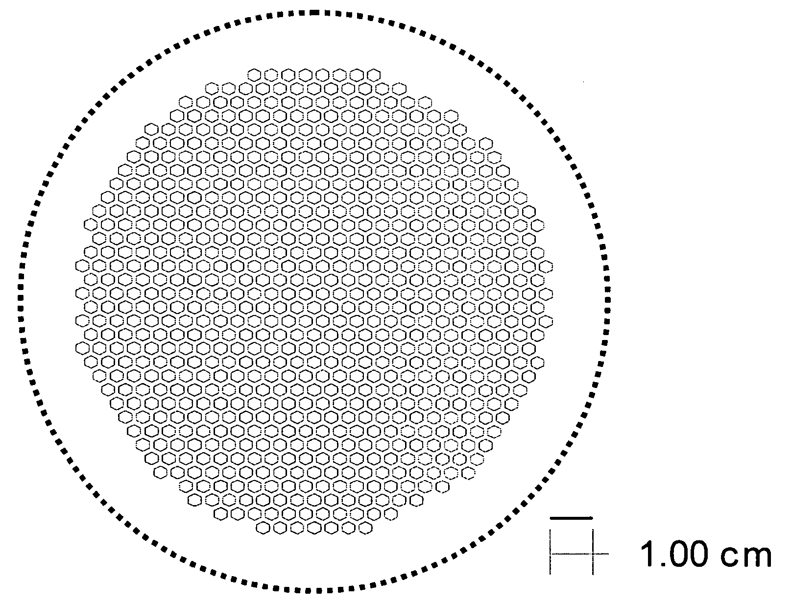
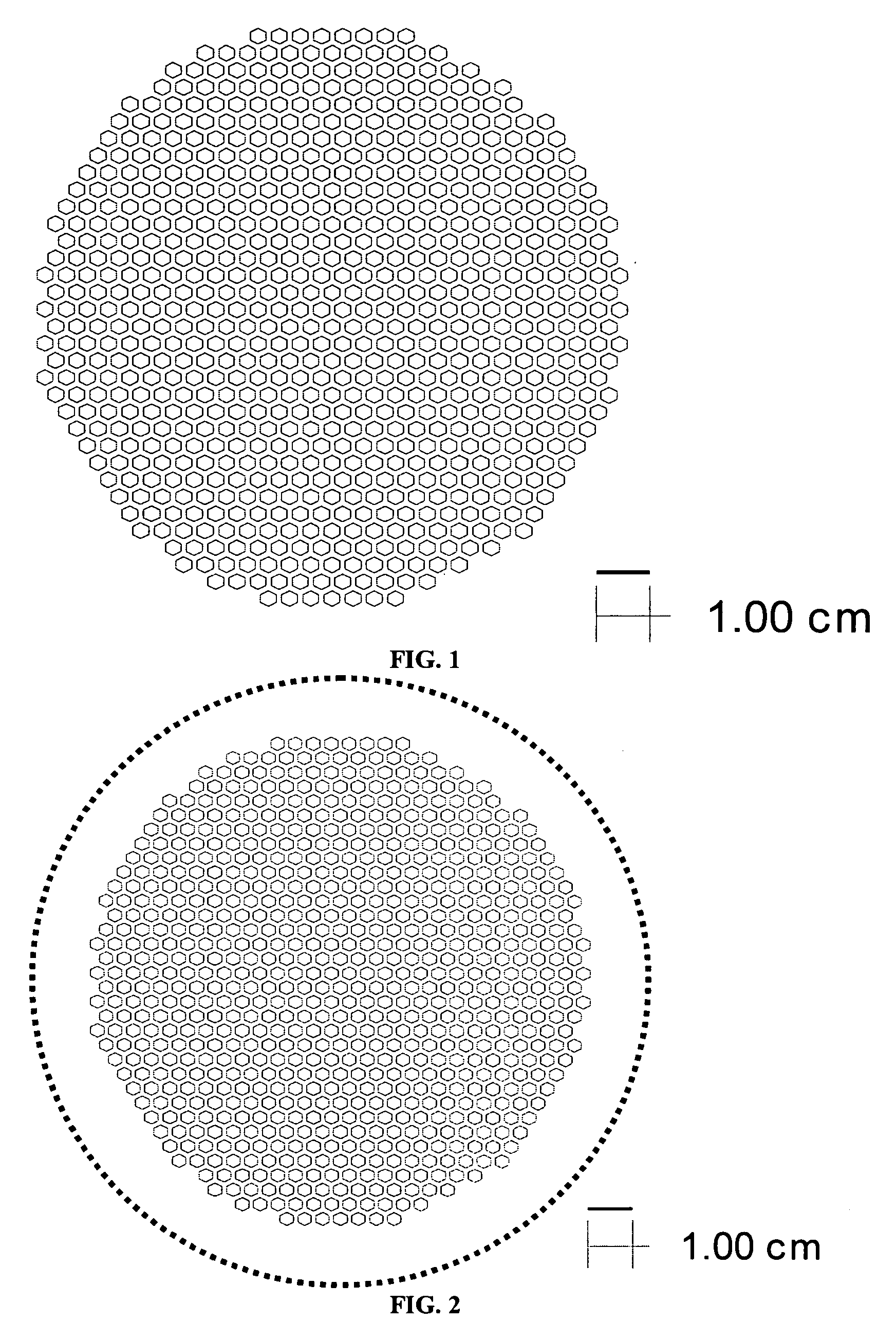
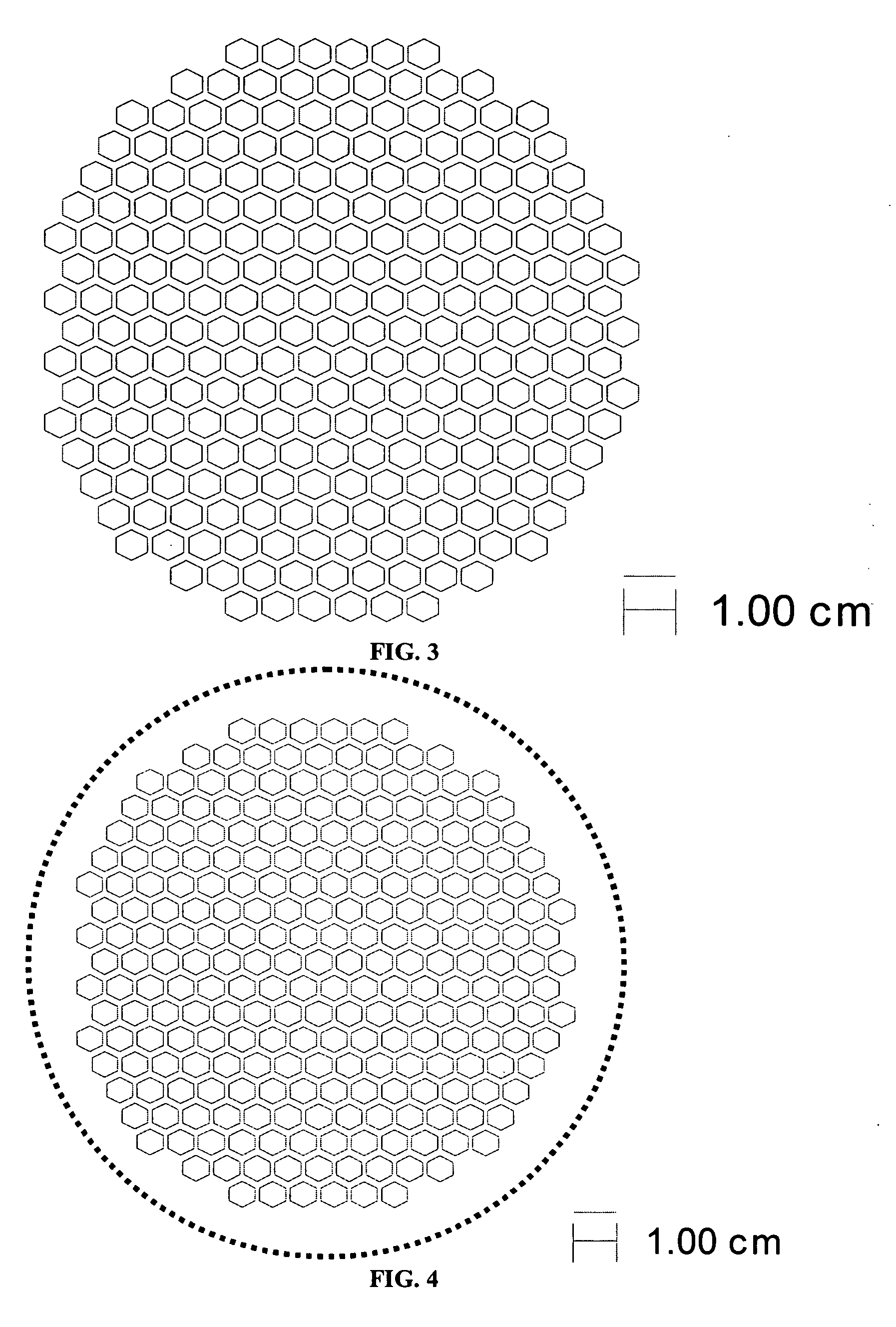
[0066] The support and electrolyte bi-layers were prepared, cast, and laminated as described in Example 1. The support laminate was laser cut to produce the pattern shown in FIG. 3. The cut-out laminate was set aside. The electrolyte stack was prepared and the two-sheet stack of electrolyte tape was laminated with the cut-out support, also as described in Example 1. The final part was cut out of the resulting laminate using the pattern shown by the solid line in FIG. 4.

example 3

Preparation of Cell Architecture III

[0067] The support and electrolyte bi-layers were prepared, cast and laminated as described in Example 1. The support laminate was laser cut to produce the pattern shown in FIG. 5. The cut-out laminate was set aside. The electrolyte stack was prepared and the two-sheet stack of electrolyte tape was laminated with the cut-out support, also as described in Example 1. The final part was cut out of the laminate using the pattern shown by the solid line in FIG. 6.


PUM


Abstract

Self-supporting thin film membranes of ceramic materials and related electrochemical cells and cell stacks. The membrane structure is divided into a plurality of self-supporting thin membrane regions by a network of thicker integrated support ribs. The membrane structure may be prepared by laminating a thin electrolyte layer with a thicker ceramic layer that forms a network of support ribs.

Description

CROSS-REFERENCE TO RELATED APPLICATIONS [0001] Not applicable STATEMENT REGARDING FEDERALLY SPONSORED RESEARCH [0002] Not applicable REFERENCE TO MICROFICHE APPENDIX [0003] Not applicable FIELD OF THE INVENTION [0004] The invention relates to self-supporting thin film membranes of ceramic materials, electrochemical cells including these thin film membranes, and stacks formed from these electrochemical cells. The disclosed membrane and resultant cell and stack architecture are particularly well suited to applications in which mechanical ruggedness and volumetric and gravimetric reaction density are desirable. This invention may be useful in electrochemical separations and catalytic reactors including but not limited to solid oxide fuel cells and oxygen separation membranes. BACKGROUND OF THE INVENTION [0005] Tubular solid oxide fuel cells (SOFCs) are the most extensively demonstrated of the many designs proposed for SOFCs. In these structures, a multi-layer tube is fabricated with ca...

Claims


Application Information

Patent Timeline
IPC IPC(8): H01M8/12H01M4/90B05D5/12H01M4/88
CPCB01D67/0041B01D2325/26B01D69/10B01D71/024C01B13/0255H01M4/8828H01M4/8839H01M4/8889H01M4/9033H01M4/9066H01M8/1226H01M8/1253H01M2300/0077H01M2300/0094Y02E60/521Y02E60/525B01D2325/08B01D69/06Y02E60/50Y02P70/50H01M8/12H01M4/90B05D5/12B01D69/061B01D67/00411B01D69/108
Inventor DAY, MICHAEL J.SABOLSKY, KATARZYNALESOUSKY, TODD G.SEABAUGH, MATTHEW M.
Owner NEXCERIS INNOVATION HLDG LLC
Why Eureka
Try Eureka