Imprinting a substrate for separation of a target molecule from a fluid medium

a technology for imprinting substrates and target molecules, which is applied in the direction of other chemical processes, instruments, transportation and packaging, etc., can solve the problems of difficult polymerization in their presence, few successful attempts to imprint proteins, and the possibility of forming h-bonds between the two functional monomers, etc., to achieve high selective recognition and binding sites, and simplify the process of the process.

Inactive Publication Date: 2007-06-07
RENESSELAER POLYTECHNIC INST
View PDF0 Cites 20 Cited by
  • Summary
  • Abstract
  • Description
  • Claims
  • Application Information

AI Technical Summary

Benefits of technology

[0026] The present invention overcomes these deficiencies. The need for substantial amounts of the print molecule can be somewhat alleviated by the number of cycles an MIP can be reused before loss of selectivity (Haupt et al., Trends in Biotechnol (1998), which is hereby incorporated by reference in its entirety). The low capacity of the current molecularly imprinted polymers employed (Wulff, Angewandte Chemie Int. Ed. EngI. 34:1812 (1995), which is hereby incorporated by reference in its entirety) (i.e. only ˜90% of the templates incorporated in the polymer can be removed and only ˜80% of the sites left behind can be reoccupied for covalent molecular imprinting and only ˜10-15% of the sites can be reoccupied for non-covalent molecular imprinting) is obviated by using surface imprinting, because less template molecules are needed and the efficiency for removal and reoccupation is far higher than the above numbers. The heterogeneity of the binding sites is a common feature of MIP (Mosbach et al., Bio / Technology 14:163 (1996), which is hereby incorporated by reference in its entirety), because of different modes of interactions of the template molecule with the polymer in different sites and swelling of these sites. Also, when the beads or substrates are prepared by crushing the solid to expose the active sites, different geometric cavities are exposed, resulting in different interactions and loss of sensitivity. Site heterogeneity leads to peak tailing in chiral separations and polyclonality and loss of specificity in the case of artificial antibodies. In fact, all separations on molecularly imprinted polymers show a significant increase in the tailing of the peak of the imprint molecule. Mass transfer limitations are alleviated by the use in surface imprinting of well-characterized and stable commercial membranes and convective flow in membrane imprinted pores which is significantly faster than diffusion in molecularly imprinted polymer beads. Surface imprinting can alleviate any restriction to imprinting small molecules, environmental concerns, and the inability to imprint biological molecules in organic media by use of aqueous solutions.
[0027] Thus, surface imprinting on synthetic commercial membranes addresses these limitations by requiring less imprint molecules (as none is needed in the polymer interior), increasing site capacity, access and speed of the imprint molecules for the imprint sites, reduce tailing with increased mass transfer, and allowing imprinting with larger molecules of biological interest in aqueous environnents.

Problems solved by technology

One problem with this combination is the possibility of forming H-bonds between the two functional monomers.
While numerous reports of molecular imprints of small molecules exist in the literature, very few successful attempts seem to have been made to imprint proteins.
As has been pointed out earlier (Haupt et al., Trends in Biotechnol (1998)), the limitations are related to the labile and flexible nature of proteins thus making polymerization in their presence difficult.
However, the selectivity was lost in aqueous environments.
Although this approach by Shi et al., Nature 387:593 (1999) is elegant and the separation factors for protein recovery from binary mixtures are reasonably high, the method is complicated and“backwards”—i.e. the flat mica surface on which the protein is originally placed needs to be peeled away to expose the imprinted cavity.
Adapting this technology from a flat surface with low surface area to a geometry with high surface area (i.e. porous beads or membranes) will be difficult.
As mentioned above, large imprint molecules, such as proteins, offer difficulties for traditional polymer imprinting methods, because they are labile and flexible making the formation of a stable rigid structure troublesome.
This problem, slow diffusion, is exacerbated with large biological molecules, such as peptides and proteins.
Two of the chief problems in producing molecularly imprinted membranes have been the rigid gel type matrices and the low capacity of imprinted sites commonly employed for molecular imprinting.
These matrices are unsuitable for producing membranes due to their low porosities and resulting lower fluxes.
The permeation rates were, however, low.
The main complication here was the need to prepare a special photo-active membrane surface so that photo-oxidation and radical polymerization could be used to form the imprinted gel layer.

Method used


Image

  • Imprinting a substrate for separation of a target molecule from a fluid medium
  • Imprinting a substrate for separation of a target molecule from a fluid medium
  • Imprinting a substrate for separation of a target molecule from a fluid medium

Examples


example 1

Materials

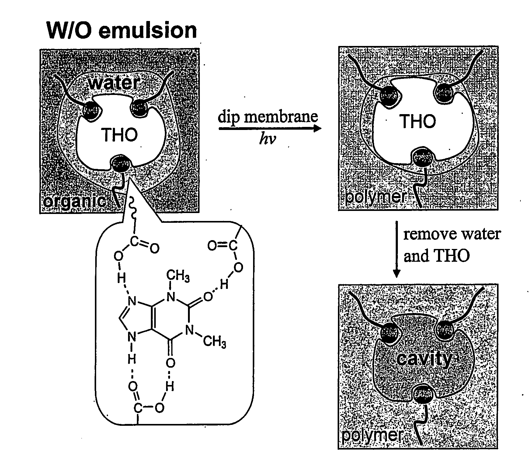
[0072] Toluene, mesitylene (1,3,5-trimethylbenzene), oleic acid, 2-(trifluoromethyl)acrylic acid (“TFMAA”), theophylline (“THO”: 1,3-Dimethylxanthine), and caffeine (“CAF”: 1,3,7-Triinethylxanthine) were purchased from Sigma-Aldrich Co. Divinylbenzene (“DVB”, Aldrich Chemical Co.) was used after treatment with silica gel to remove an inhibitor (FIG. 6). Polypropylene (“PP”) membranes (Celgard®2500 microporous flat sheet polypropylene membrane, thickness: 25 μm, porosity: 55%, pore size: 0.05-0.2 μm wide 0.2-0.5 μm long, Celgard Inc., Charlotte, N.C.) were used as microporous substrates.

example 2

Preparation of Molecularly Imprinted Polymer

[0073] 0.56 g(2.0×10⁻³ mol) of oleic acid, 0.28 g(2.0×10⁻³ mol) of 2-(trifluoromethyl)acrylic acid (“TFMAA”), and 0.23 g (3.0×10⁻⁴ mol) of N-ribitol L-glutamic acid dioleyl diester (2C18Δ9GE, emulsion stabilizer14) were dissolved in 60 ml of toluene / DVB (1:2 (v / v)), which was mixed with 30 ml aqueous solution containing 0.14 g (8×10⁻⁴ mol) of theophylline. Although methacrylic acid (“MAA”, pKa=4.6) and TFMAA (pKa=2.3) have been used as functional monomers for various template molecules, TFMAA was chosen since it was more acidic and could increase hydrogen-bonding with the template (Mosbach et al., J. Am. Chem. Soc. 123:12420-12421 (2001); Matsui et al., Anal Chem. 72:3286 (2000); and Yilmaz et al., Angew. Chem. Int. Ed. 39:2115-2118 (2000), which are hereby incorporated by reference in its entirety). Using only oleic acid (without TFMAA) as a functional monomer, selectivity for THO over CAF was hardly noticeable. The mixture was sonicated...

example 3

Characterization

[0075] Attenuated total reflection Fourier transform infrared spectroscopy (“ATR / FT-IR”) (Magna-IR 550 Series II, Nicolet Instruments, Madison, Wis.) was used to confirm polymerization and to measure the degree of grafting onto the polypropylene membrane under UV irradiation. Using an incident angle of 45°, the penetration of IR sample depth was approximately 0.1-1.0 μm (Nicolet User's Manual for Infrared Spectrometer, Model# 0012-490(T) Nicolet Magna-IR, Thermo Nicolet Corp, Madison, Wis., which is hereby incorporated by reference in its entirety). Each spectrum was recorded at aresolution of 4.0 cm−1. The absorbance peak heights at 1376, and 1458 cm−1 were due to C—H bending of polypropylene membrane (Wang et al., J. Chem. Tech. Biotech. 70:355-362 (1997) and Pretsch et al., Table of Spectral Data for Structure Determination of Organic Compounds 2nd ed.; Fresenius, W., Huber, J. K. F., Pungor, E., Rechnitz, G. A., Simon, W., West, Th. S., Eds.; Springer-Verlag: Be...


PUM

PropertyMeasurementUnit
hydrophilicaaaaaaaaaa
hydrophobicaaaaaaaaaa
emulsionaaaaaaaaaa

Abstract

The present invention is directed to a method of producing a substrate suitable for separation of a target molecule from a fluid medium. This method includes providing an emulsion comprising a water phase in an oil phase, where the oil phase contains a polymerizable monomer and the water phase contains the target molecule. The substrate, having pores extending from one side of the substrate to another side of the substrate, is coated with the emulsion, and the monomer in the emulsion coated substrate is then polymerized. The water and target molecule are removed from the polymerized, emulsion coated substrate. As a result, the substrate is imprinted with the target molecule and, therefore, is suitable for separation of the target molecule from a fluid medium. The resulting article and its use are also disclosed.

Description

[0001] This application claims benefit of U.S. Provisional Patent Application Ser. Nos. 60 / 403,530, filed Aug. 14, 2002, and 60 / 462,356, filed Apr. 11, 2003.FIELD OF THE INVENTION [0002] The present invention relates to a method of producing a substrate suitable for separating a target molecule from a fluid medium, an article containing that substrate, and method of using that article to separate a target molecule from a fluid medium. BACKGROUND OF THE INVENTION [0003] The concept of molecular imprinting is depicted in FIG. 1 (Haupt et al., Trends in Biotechnol (1998)). The molecule to be imprinted is first allowed to form bonds with polymerizable functional groups, which are then crosslinked. Following extraction of the print or template molecule, specific recognition sites are left in the polymer where the spatial arrangement of the polymer network and the immobilized functional groups correspond to the geometry and chemistry of the imprinted molecule. [0004] Molecular imprinting ...

Claims


Application Information

Patent Timeline
Patent Type & Authority Applications(United States)
IPC IPC(8): C08F2/46B05D3/02B32B3/26B01J20/28B01J20/30B01J20/32G01N33/543
CPCB01J20/28035B01J20/30B01J20/3057B01J20/32B01J20/3242G01N33/543G01N2600/00B01J20/3204B01J20/321B01J20/3212B01J20/3225B01J20/3248B01J20/3251B01J20/3255B01J20/3272B01J20/3274B01J20/3282Y10T428/249953
Inventor BELFORT, GEORGES J.HAN, MINAKANE, RAVINDRA S.
Owner RENESSELAER POLYTECHNIC INST
Why Eureka
Try Eureka