Layered thermal barrier coatings containing lanthanide series oxides for improved resistance to CMAS degradation

a technology of lanthanide series and thermal barrier coating, which is applied in the direction of superimposed coating process, machine/engine, natural mineral layered products, etc., can solve the problems of insufficient interaction between small amounts of lanthanide series based oxides and the formation of advanced turbine engines, and achieve the elimination of an expensive and complex inner layer, improved erosion resistance, and preventing cmas damage

Inactive Publication Date: 2007-07-12
GENERAL ELECTRIC CO
View PDF13 Cites 95 Cited by
  • Summary
  • Abstract
  • Description
  • Claims
  • Application Information

AI Technical Summary

Benefits of technology

[0018]An advantage of the present invention is that it can be utilized to prevent CMAS damages to hot section engine components that also are exposed to the environmental contaminants found in flow path air.
[0019]Another advantage of the present invention is that it can be used to replace TBC coatings in current engines during retrofit or overhauls and it can be used on new engine designs and engine variants that can experience temperatures in excess of about 2800° F.
[0020]Still another advantage of the multilayer coating of the present invention is that it will not completely spall from the hot section component even after exposure to a large number of engine cycles an

Problems solved by technology

Since CMAS results from the deposition of environmental contaminants found in the flowpath air, such as sand, dirt, volcanic ash, sulfur in the form of sulfur dioxide, fly ash flow path, particles of cement, runway dust, and other pollutants on hot sec

Method used


Image

  • Layered thermal barrier coatings containing lanthanide series oxides for improved resistance to CMAS degradation
  • Layered thermal barrier coatings containing lanthanide series oxides for improved resistance to CMAS degradation
  • Layered thermal barrier coatings containing lanthanide series oxides for improved resistance to CMAS degradation

Examples


Embodiment Construction

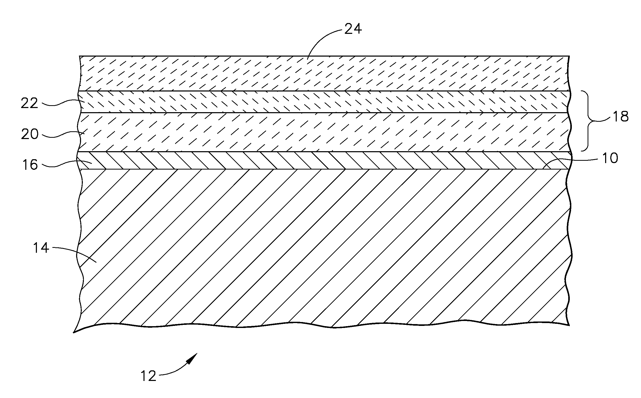
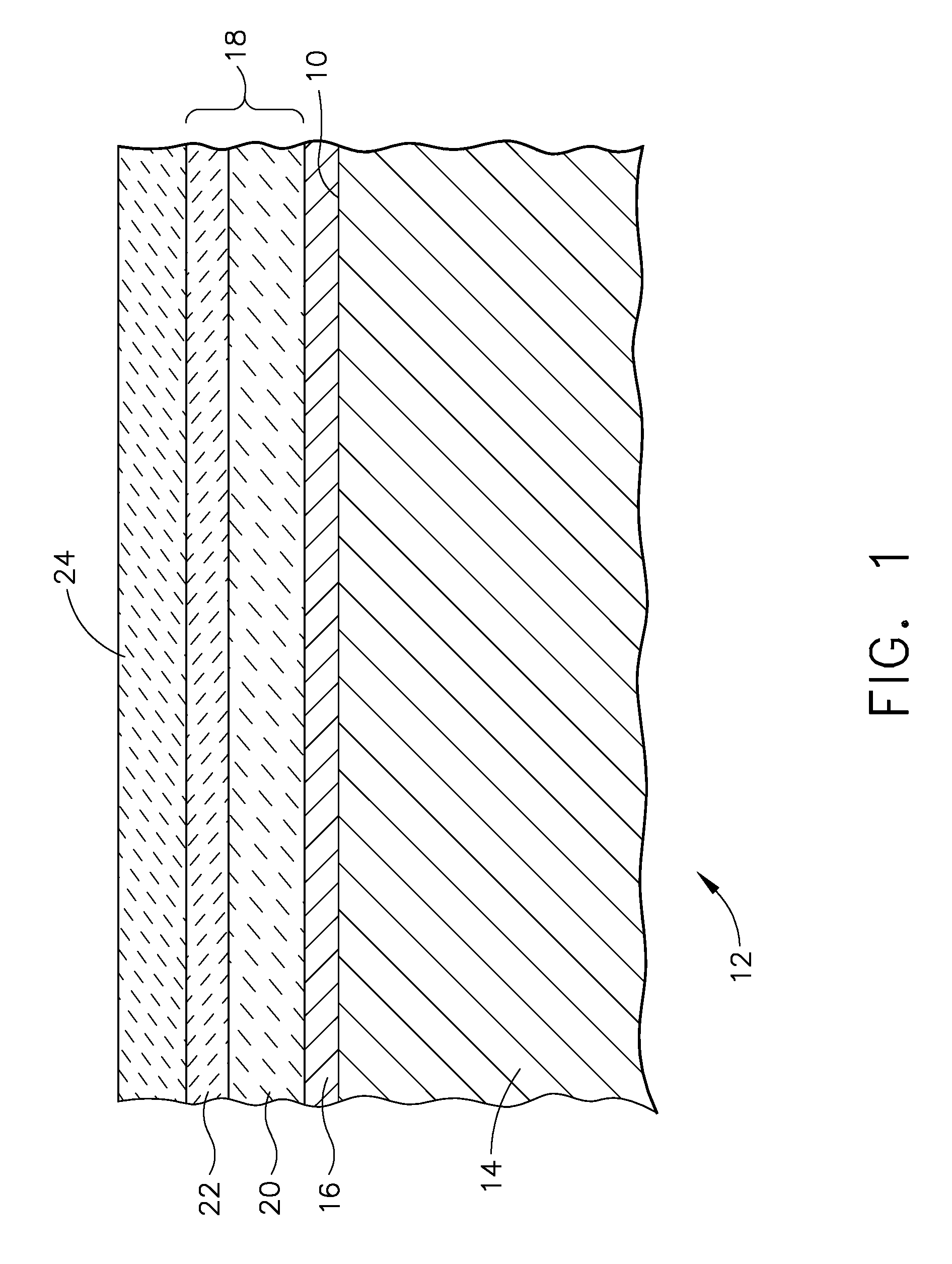
[0028]The present invention is a multi-layer thermal barrier coating system that is resistant to CMAS infiltration for application to a substrate of hot section components of gas turbine engines that are exposed to environmental contaminants resulting in CMAS deposits during normal gas turbine operation. Referring now to FIG. 1, the thermal barrier coating system typically is applied over the substrate surface 10 of a component 12. The substrate 14 typically is a superalloy material, which is coated with a bond coat 16. A zirconium-based coating 18 overlies the bond coat to provide the requisite CMAS infiltration resistance. It will be understood by those skilled in the art that coating 18 of the present invention may include hafnium, partially or completely substituted for zirconium, and is used herein in that context. The zirconium-based coating 18 includes two layers, an inner layer 20 of partially stabilized zirconium oxide and an outer layer 22 overlying the inner layer 20 comp...


PUM

PropertyMeasurementUnit
Percent by massaaaaaaaaaa
Thicknessaaaaaaaaaa

Abstract

A coating applied as a two layer system. The outer layer is an oxide of a group IV metal selected from the group consisting of zirconium oxide, hafnium oxide and combinations thereof, which are doped with an effective amount of a lanthanum series oxide. These metal oxides doped with a lanthanum series addition comprises a high weight percentage of the outer coating. As used herein, lanthanum series means an element selected from the group consisting of lanthanum (La), cerium (Ce), praseodymium (Pr), neodymium (Nd), promethium (Pm), samarium (Sm), europium (Eu), gadolinium (Gd), terbium (Tb), dysprosium (Dy), holmium (Ho), erbium (Er), thulium (Tm), ytterbium (Yb), lutetium (Lu) and combinations thereof, and lanthanum series oxides are oxides of these elements. When the zirconium oxide is doped with an effective amount of a lanthanum series oxide, a dense reaction layer is formed at the interface of the outer layer of TBC and the CMAS. This dense reaction layer prevents CMAS infiltration below it. The second layer, or inner layer underlying the outer layer, comprises a layer of partially stabilized zirconium oxide.

Description

FIELD OF THE INVENTION[0001]The present invention is directed to a multilayer coating for hot section turbine components, and more specifically for a coating that includes rare earth elements.BACKGROUND OF THE INVENTION[0002]Calcium-magnesium-aluminum-silicate (CMAS) infiltration is a phenomenon that is linked to thermal barrier coating (TBC) spallation in hot section turbine components.[0003]Thermal barrier coatings are utilized on hot section engine components including combustor section and turbine section components to protect the underlying base materials from high temperatures as a result of the flow of hot gases of combustion through the turbine. These hot gases of combustion can be above the melting point of the base materials, which typically are superalloy materials, being based on iron, nickel, cobalt and combinations thereof. Of course, the thermal barrier coatings provide passive protection from overheating, and are used in conjunction with cooling airflow that provides...

Claims


Application Information

Patent Timeline
IPC IPC(8): B32B15/04
CPCF01D5/288Y02T50/67Y02T50/671C23C28/042C23C28/048F05D2300/2118C23C28/3215C23C28/325C23C28/345C23C28/3455C23C28/36C23C28/321Y02T50/60
Inventor DAROLIA, RAMGOPALNAGARAJ, BANGALORE A.KONITZER, DOUGLAS G.GORMAN, MARK D.FU, MING
Owner GENERAL ELECTRIC CO
Why Eureka
Try Eureka