Methods of Preparing Multicolor Quantum Dot Tagged Beads and Conjugates Thereof

Inactive Publication Date: 2007-07-12
ADVANCED RES TECH INST
View PDF30 Cites 28 Cited by
  • Summary
  • Abstract
  • Description
  • Claims
  • Application Information

AI Technical Summary

Benefits of technology

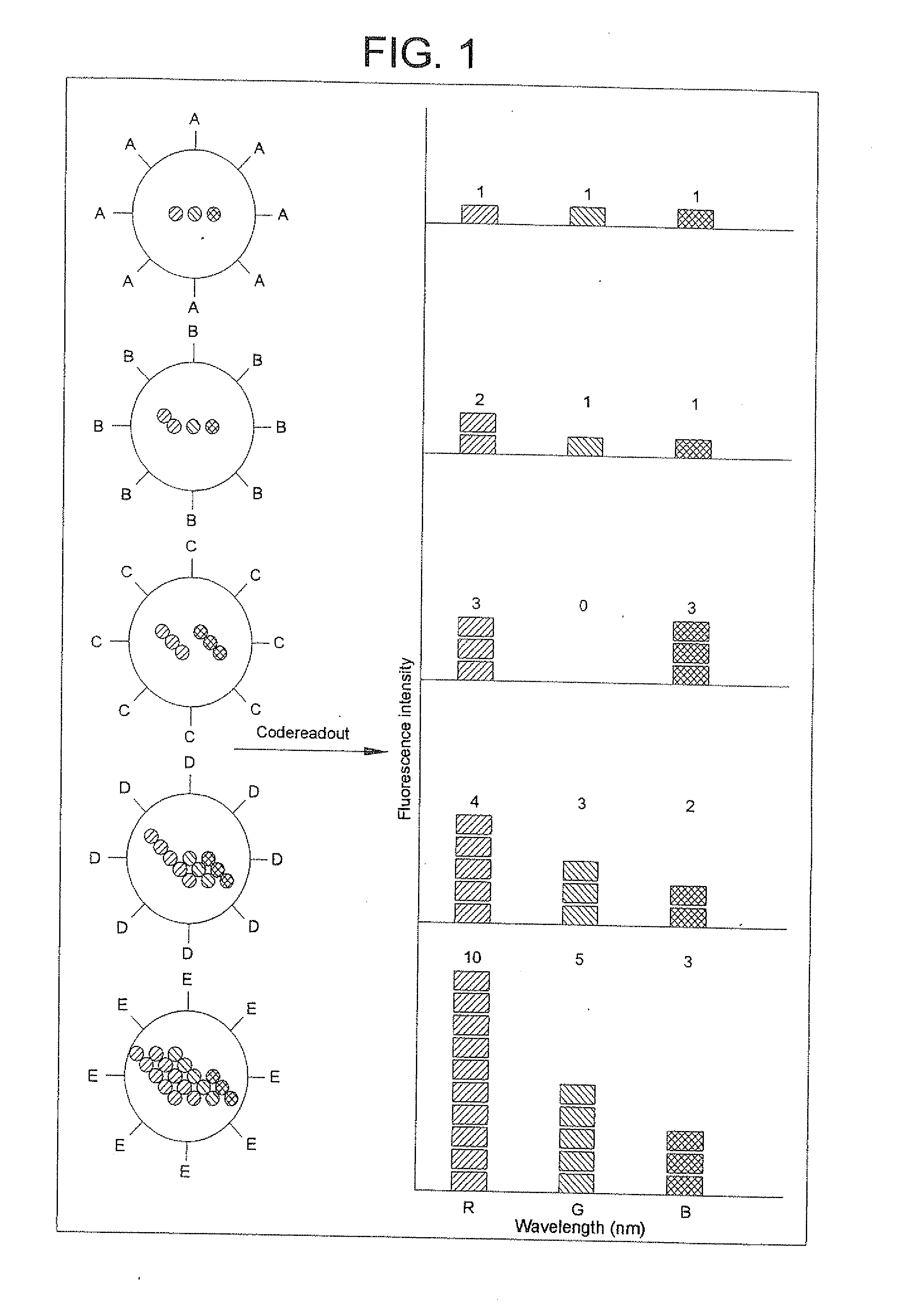
[0013] Towards the ultimate goal of better molecular target detection, the present invention permits an optical coding technology, preferably multiplexed optical coding. Such a technology allows for “lab-on-a-bead” for massively parallel and high throughput analysis of targets, in particular biological molecules. This technology is premised, at least in part, on the novel optical properties of semiconductor quantum dots and the ability to incorporate multicolor quantum dots into beads at precisely controlled ratios. Based on the ratio of quantum dots added, a unique identifiable code exists for each bead. The multicolor quantum dot-tagged beads can then be converted into a conjugate by attaching a probe to the bead. This conjugate can combine with a target, allowing for facile identification of the target.
[0016] Compared to coding systems that use organic dyes, the present invention has a number of advantages: the fluorescence emission wavelength can be continuously tuned, a single wavelength can be used for simultaneous excitation of all different colored quantum dots, the emission spectra are narrow allowing for multiple colors (i.e., wavelengths) to be used, there is no fluorescence resonance energy transfer (FRET) between the quantum dots, and the quantum dots are photostable.
[0017] The present invention also has advantages over organic dye systems in that it allows for multiplexed analysis of a large number of targets. The analysis is aided by the high stability of multicolor quantum dot-tagged beads and their ease of preparation, modification, and detection. In comparison with planar DNA chips, the encoded bead technology of the present invention is expected to be more flexible in target selection, faster in binding kinetics (similar to that in homogeneous solution), and cheaper in production. These and other objects and advantages, as well as additional inventive features, of the present invention will become apparent to one of ordinary skill in the art upon reading the detailed description provided herein.

Problems solved by technology

There are many disadvantages to using an organic dye for these fluorescent-labeling systems.
As a result, there is a severe limitation on the number of different color organic dye molecules which can be utilized simultaneously or sequentially in an analysis since it is difficult to either simultaneously or even non-simultaneously detect or discriminate between the presence of a number of different detectable substances due to the broad spectrum emissions and emission tails of the labeling molecules.
Another problem is that organic dyes often have a narrow absorption spectrum (about 30-50 nm), thus requiring either multiple wavelength probes, or else broad spectrum excitation source which is sequentially used with different filters for sequential excitation of a series of probes respectively excited at different wavelengths.
Another problem associated with organic dyes is their lack of photostability.
However, these previous studies were based on organic dyes and lanthanide complexes, and were limited by the unfavorable absorption and emission properties of these materials (e.g., inability to excite more than 2-3 fluorophores, broad and asymmetric emission profiles, and spectral overlapping).
Systems comprising two (or more) organic dyes embedded in beads are prone to fluorescence resonance energy transfer (FRET), the emission spectra of the beads with the organic dyes embedded are not predictable and therefore prove unreliable, and cannot be detected by a wavelength-resolved spectroscopy combined with a microchannel.
Moreover, organic dyes cannot have continuously tunable emission wavelengths.
Finally, because different organic dyes are soluble in solvents to varying degrees of solubility, the dyes cannot be embedded in the beads in a precisely controlled ratio.
This drawback severely limits the number of beads useful for multiplexed analysis of targets.
However, none of these approaches provide beads that contain quantum dots embedded therein in a precisely controlled ratio and reproducible manner.
Furthermore, since the number and size (i.e., color) of quantum dots that enter the bead's interior versus those that remain on the bead surface cannot be controlled, the resulting quantum dot-tagged beads are not very reproducible compared to each other and batch to batch.
Exposing water-soluble quantum dots to heat causes the QDs to become unstable.

Method used


Image

  • Methods of Preparing Multicolor Quantum Dot Tagged Beads and Conjugates Thereof
  • Methods of Preparing Multicolor Quantum Dot Tagged Beads and Conjugates Thereof
  • Methods of Preparing Multicolor Quantum Dot Tagged Beads and Conjugates Thereof

Examples


example 1

[0092] This example illustrates the formation of polymer beads formed by standard emulsion polymerization.

[0093] Polystyrene beads were synthesized by using standard oil and water (o / w) emulsion polymerization at 70° C. in the following methods:

[0094] In the first method, the oil phase consisted of styrene (98% v / v), divinylbenzene (1% v / v), and acrylic acid or a derivative such as mono-2-methacryloyloxyethyl succinate (1% v / v) in the presence of the radical initiator AIBN and stabilizer SDS.

[0095] In the second method, the oil phase consisted of styrene (93% v / v), divinylbenzene (1% v / v), acrylic acid or a derivative such as mono-2-methacryloyloxyethyl succinate (1% v / v), and 5% dodecane (or octane, decane) in the presence of the radical initiator AIBN and stabilizer SDS. P. A. Lovell, Mohamed S. El-Aasser, “Emulsion polymerization and emulsion polymerization”, Wiley, Inc., (1997).

example 2

[0096] This example illustrates the formation of porous polymer beads by successive seeded emulsion polymerization.

[0097] In this procedure, small latex particles (100200 nm diameter) were grown to larger sizes in the presence of a monomer, an initiator, and an emulsifier. In one example, a mixture was formulated from 10 ml polystyrene seed particles, 20 ml distilled water, 3 ml cyclohexane, 50 μl acrylic acid, 4 ml styrene, 200 μl divinylbenzene, 10 mg benzoyl peroxide, and 30 mg sodium dodecylsulfonate (SDS). The mixture was stirred at room temperature for 18 hours to allow the monomer and the cross-linking reagent to swell the seeds. A stream of nitrogen gas was then purged into the mixture for five minutes, and the temperature of the reaction mixture was raised to 75° C. After 15 hours, the mixture yielded a suspension of polystyrene particles (1-10 μm), with a size distribution of 2-3%.

example 3

[0098] This example illustrates the formation of porous polymer beads by two-stage seeded polymerization.

[0099] In the first stage, 0.2 ml of dibutyl phthalate (DBP) was emulsified within 15 ml of an aqueous medium containing 0.25% (w / w) sodium dodecyl sulfate (SDS). About 1 ml of the aqueous suspension including 120 mg polystyrene seed particles (100-200 nm diameter) was added into the aqueous DBP emulsion. The resulting suspension was stirred at room temperature until all of the emulsified liquid was transferred into the particles (about 5 hours).

[0100] In the second stage, DBP-swollen seed particles were further swelled in the monomer phase (containing 0.3 ml of styrene, 0.3 ml of DVB, 10 μl acrylic acid, and 40 mg of benzoyl peroxide). About 0.6 ml of the monomer phase was emulsified by ultrasonication in 15 ml of the aqueous medium. The monomer emulsion was then mixed with the aqueous suspension of DBP-swollen seed particles. The absorption of monomer phase by the DBP-swollen...


PUM

PropertyMeasurementUnit
Percent by volumeaaaaaaaaaa
Nanoscale particle sizeaaaaaaaaaa
Volumeaaaaaaaaaa

Abstract

The present invention provides a method of preparing a multicolor quantum dot-tagged bead, a multicolor quantum dot-tagged bead, a conjugate thereof, and a composition comprising such a bead or conjugate. Additionally, the present invention provides a method of making a conjugate thereof and methods of using a conjugate for multiplexed analysis of target molecules.

Description

CROSS-REFERENCE TO RELATED PATENT APPLICATIONS [0001] This patent application is a continuation of U.S. patent application Ser. No. 10 / 185,226, filed on Jun. 28, 2002, which claims the benefit of U.S. Provisional Patent Application No. 60 / 301,573, filed Jun. 28, 2001, all of which are hereby incorporated in its entirety by reference.GOVERNMENT SUPPORT [0002] This invention was made in part with Government support under Grant Numbers R01GM60562 and FG02-98ER14873 awarded by the National Institutes of Health and the Department of Energy. The Government may have certain rights in this invention.TECHNICAL FIELD OF THE INVENTION [0003] The present invention relates to methods of obtaining a multicolor quantum dot-tagged bead, multicolor quantum dot-tagged beads, a conjugate thereof and a composition comprising such a quantum dot-tagged bead or conjugate. Additionally, the present invention relates to methods of using a conjugate for multiplexed detection of targets, in particular biomole...

Claims


Application Information

Patent Timeline
IPC IPC(8): G01N33/53B05D3/00G01N33/545C12N15/09C12Q1/68G01N21/77G01N21/78G01N33/543G01N33/544G01N33/569G01N33/58
CPCB82Y15/00G01N33/588G01N33/544G01N33/54393
Inventor NIE, SHUMINGGAO, XIAOHUHAN, MINGYONG
Owner ADVANCED RES TECH INST
Why Eureka
Try Eureka