Heat-resistive catalyst and production method thereof

Inactive Publication Date: 2007-07-19
NISSAN MOTOR CO LTD
View PDF18 Cites 21 Cited by
  • Summary
  • Abstract
  • Description
  • Claims
  • Application Information

AI Technical Summary

Benefits of technology

[0008] However, it is difficult for the method described to form a desirable composite of noble metal particles and co-catalytic metal particles, so that the contact area between noble metal particle and co-catalytic metal particle is reduced to be insuff

Problems solved by technology
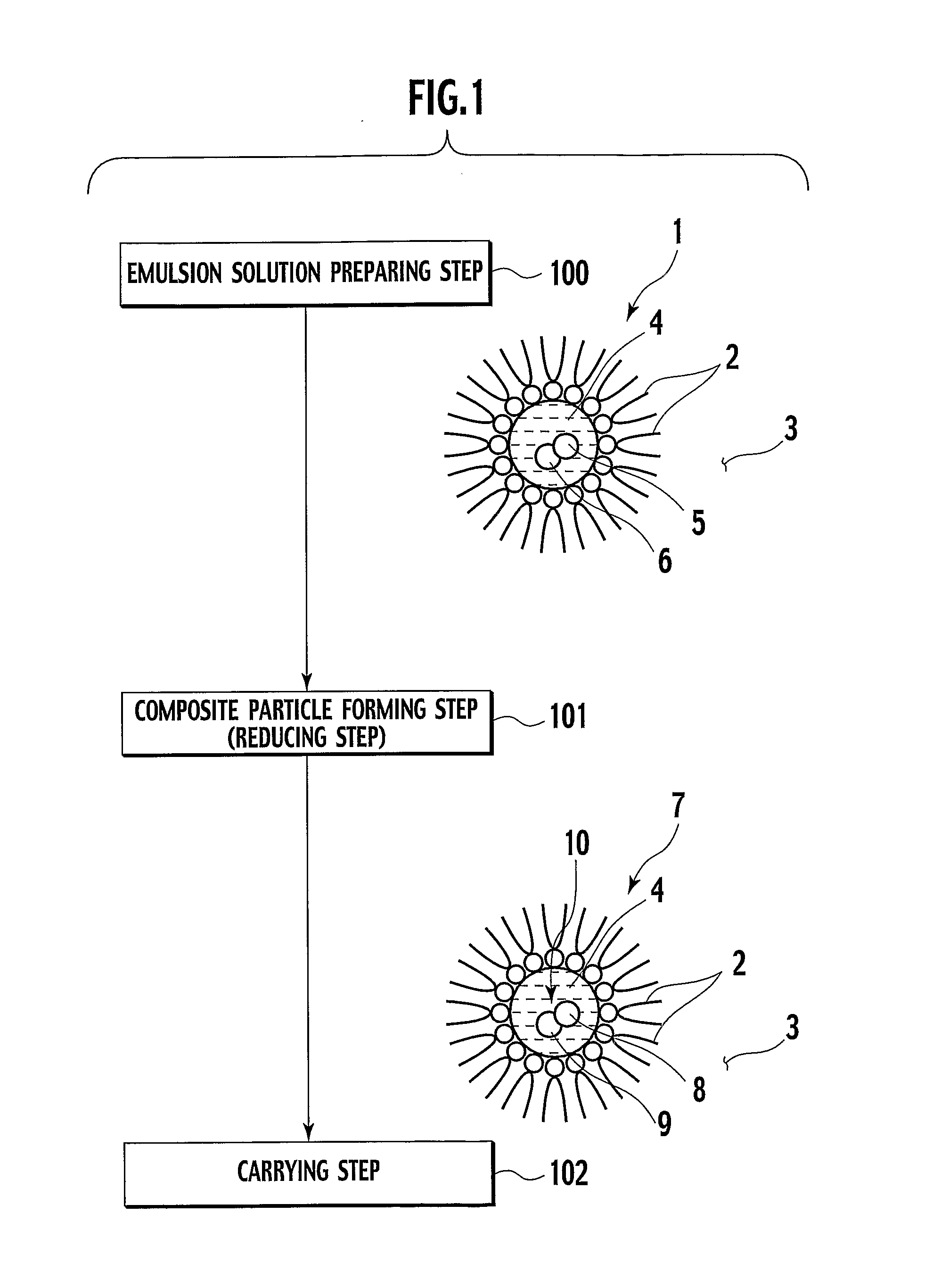
However, it is difficult for the method described to form a desirable composite of noble metal particles and co-catalytic metal particles, so that the contact area between noble m

Method used


Image

  • Heat-resistive catalyst and production method thereof
  • Heat-resistive catalyst and production method thereof
  • Heat-resistive catalyst and production method thereof

Examples


example 1

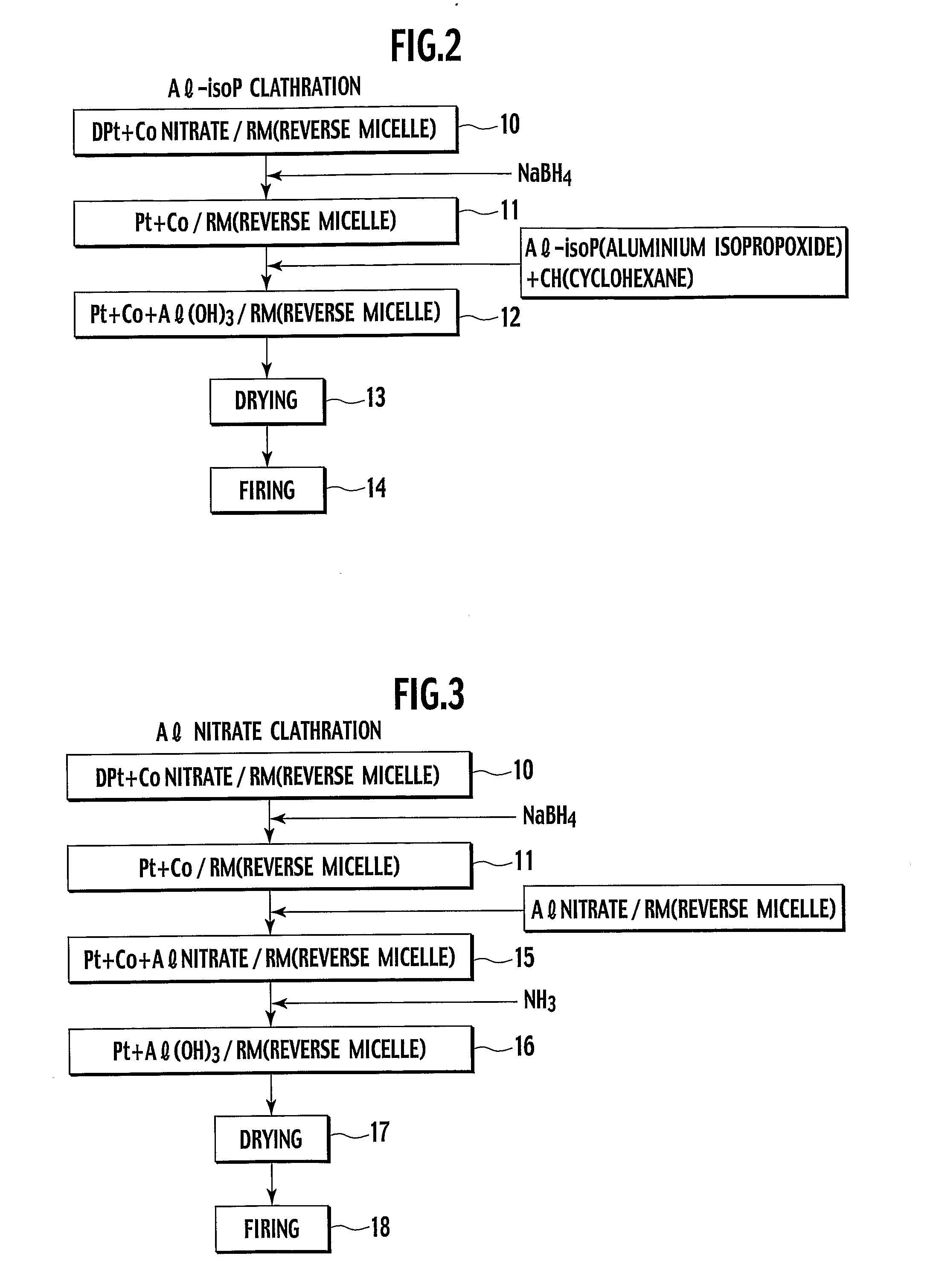
[0062] In Example 1, a catalyst powder was created by co-reduction in aluminium isopropoxide (Al-isoP) clathrate compound in FIG. 2.

[0063] Added to 66 g of polyethylene glycol (5) mono-4-nonylphenyl ether as a surfactant was 1000 ml of cyclohexane as solvent, thereby preparing a solution including 0.15 mol % of surfactant, and the solution was then stirred. Meanwhile, added into 7.73 ml of pure water were 0.37 g of dinitro-diamine Pt nitric acid-acidic aqueous solution (Pt concentration was 8.46 wt. %) and 0.26 g of cobalt nitrate hexahydrate powder, and they were there after mixed and stirred. Thereafter, the prepared solutions were mixed, and stirred for about 2 hours, thereby subsequently obtaining reverse micellar solution including ions of Pt and Co (step 10).

[0064] Next, 0.12 g of NaBH4 was added to the emulsion, followed by stirring for 2 hours, thereby obtaining reverse micellar solution including reduced composite particles (Pt—Co) (step 11).

[0065] Further, there was pre...

example 2

[0068] The same procedure as Example 1 was used except that 0.16 g of hydrazine was added instead of NaBH4 in the step 11 in Example 1, thereby creating catalyst powder of Example 2. Further, 500 g of thus obtained catalyst powder was used and coated onto a honeycomb carrier like to the procedure of Example 1, thereby obtaining a catalyst of Example 2.

example 3

[0069] In Example 3, a catalyst powder was created by co-reduction in Al nitrate clathrate compound in FIG. 3.

[0070] The same procedure as Example 1 was used up to the step 11, while using a nickel nitrate hexahydrate powder as the metal in the step 10 for Example 1. Here, an Al nitrate solution obtained by adding 7.36 g of Al nitrate to 2 ml of pure water, was added and mixed into a solution obtained by adding 225.7 ml of cyclohexane to 14.9 g of polyethylene glycol(5) mono-4-nonylphenyl ether, followed by stirring for about 2 hours, thereby preparing reverse micellar solution containing Al nitrate.

[0071] The reverse micellar solution including Pt—Ni composite particle and the reverse micellar solution Al nitrate were mixed, followed by stirring for about 2 hours, thereby obtaining reverse micellar solution in which Pt—Ni composite particle is mixed with Al nitrate (step 15).

[0072] Dropped into this emulsion was 70.5 g of 25% ammonia water, whereby the Al nitrate was insolubiliz...


PUM


Abstract

A high heat-resistive catalyser formed as a catalyst including a composite particle composed of a noble metal particle and a co-catalytic metal compound particle contacting, as a metal or as an oxide, with the noble metal particle, and a substrate carrying the noble metal particle and the co-catalytic metal compound particle, is produced by having a noble metal salt aqueous solution and a co-catalytic metal salt aqueous solution concurrently provided in a reverse micelle preparing reverse micellar solution containing a noble metal precursor and a co-catalytic metal precursor, and having a substrate carrying a composite particle comprising the noble metal precursor and the co-catalytic metal precursor concurrently reduced as a noble metal particle and a co-catalytic metal particle, respectively.

Description

TECHNICAL FIELD [0001] The present invention relates to a heat-resistive catalyst adaptive as an exhaust-gas purifying catalyser to be mounted on a vehicle, and to a production method thereof. BACKGROUND ART [0002] Along with a rising interest to the environment in recent years, the regulation to exhaust gases of automobile has been tightened with an increasing severity, involving improvements in engine system, accompanied by investigations for enhancement in performance of catalyst for purifying exhaust gases. [0003] The exhaust-gas purifying catalyst has noble metal particles (e.g. of platinum (Pt), palladium (Pd)) held on surfaces of a carrying substrate (e.g. alumina (Al2O3)), for a conversion of harmful components (e.g. unburnt hydrocarbons (HC), carbon monoxide (CO)) contained in exhaust gases, by oxidization on noble metal particles, into harmless components (e.g. water, gas). [0004] Noble metals to be active in catalysis are extremely expensive elements with an anxiety of re...

Claims


Application Information

Patent Timeline
IPC IPC(8): B01J23/00B01J21/00B01D53/94F01N3/10B01J23/38B01J23/46B01J23/56B01J23/63B01J23/89B01J35/00B01J37/03B01J37/16C04B38/00
CPCB01J23/38B01J23/56B01J23/89B01J23/8913B82Y30/00B01J23/894B01J35/0013B01J35/04B01J37/16B01J23/892
Inventor SHIRATORI, KAZUYUKISUGA, KATSUONAKAMURA, MASANORIWAKAMATSU, HIRONORIYASUDA, HIROFUMI
Owner NISSAN MOTOR CO LTD
Why Eureka
Try Eureka