[0020] Typical HPM and TED
threat sources are expected to generate significant signal energy over a range from hundreds of MHz to multiple GHz in frequency. This implies the need for antenna structures that exhibit relatively flat amplitude-bandwidth response over a decade or more in frequency. Conical monopole structures working against a
ground plane have been shown in literature and practice to exhibit such
wideband response. A somewhat similar response is possible in a planar structure in the form of a triangular shape monopole element working against a
ground plane. The planar arrangement is easier to manufacture in the form of a
printed circuit board (PCB) versus a three-dimensional metallic structure, such as a conic shape. A significant challenge to the performance of wideband antennae is encountered in the conventional approach of first optimally matching the antenna source impedance to a
transmission line which is used to convey the received signals to a remotely-located
detector. The
antenna impedance typically varies greatly over the frequency range of interest making the wideband
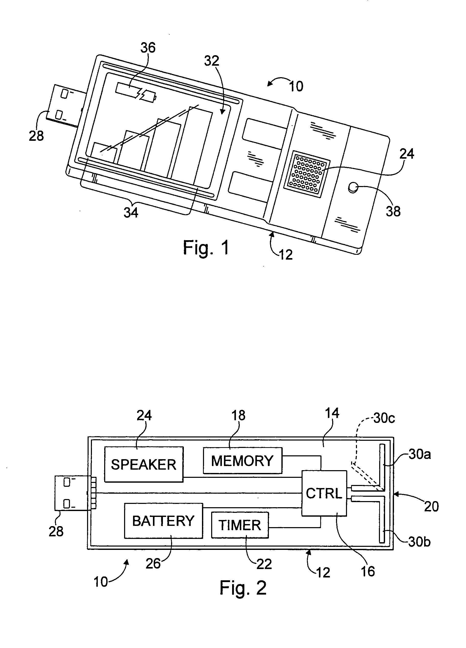
impedance matching difficult. This difficulty can be mitigated for the case of simple envelope detection by incorporating the
envelope detector into the antenna structure with no intervening
transmission line. Here, the
envelope detector signal output is applied to an
amplifier having high-
input impedance to avoid significant loading of the
detector elements. The amplified signal output is then available for further
signal processing.
[0022] This example antenna /
detector element has the feature of simple combining of multiple elements to recover the peak detected level of two or three (or more) elements. This is possible by simple parallel connection of the detector outputs at the high-impedance
amplifier input since the individual detector outputs are diodes. The rectified signal of the antenna / detector element receiving the highest RF signal is passed on to the high-impedance
amplifier without significant loading by the other antenna elements.
[0026] The directional-sensing wideband
frequency detection device may include a fifth detector unit centrally situated along a third axis in a second plane, wherein the third axis is perpendicular to the first and second axis and intersects the first and second axis at the point of intersection of the first and second axis, wherein the point of intersection of the first and second axis is substantially
equidistant from the first, second, third, fourth, and fifth detector units. Furthermore, the directional-sensing wideband
frequency detection device may also include a sixth detector unit centrally situated along the third axis in the second plane, wherein the point of intersection of the first and second axis is substantially
equidistant from the first, second, third, fourth, fifth, and sixth detector units. The fifth and sixth detector units may provide a vector in a third dimension in order to facilitate resolution of directional finding bearings in three dimensions (e.g.,
azimuth angle and
elevation angle).
[0032] In many conventional DF systems,
sector antenna outputs are coupled via
RF transmission lines to receive
electronics for
processing. Prior art sector antennae are relatively limited in the following desirable simultaneous properties: sensitivity to signals over a wide frequency range and wide range of signal polarization orientations and relatively uniform beam width over that frequency range and the ability to efficiently couple the signals to a
transmission line to convey to
signal processing electronics equipment. The present DF
system invention achieves the aforementioned bandwidth, beam width and arbitrary polarization sensitivity properties by incorporating
diode envelope detectors within each
sector antenna / detector unit. This design relieves the requirement to efficiently couple the recovered RF signals to a transmission line to convey to
processing electronics. In this design, only the detected (
baseband) envelope information of the detected RF signal is conveyed to the
processing electronics. Accordingly, the DF
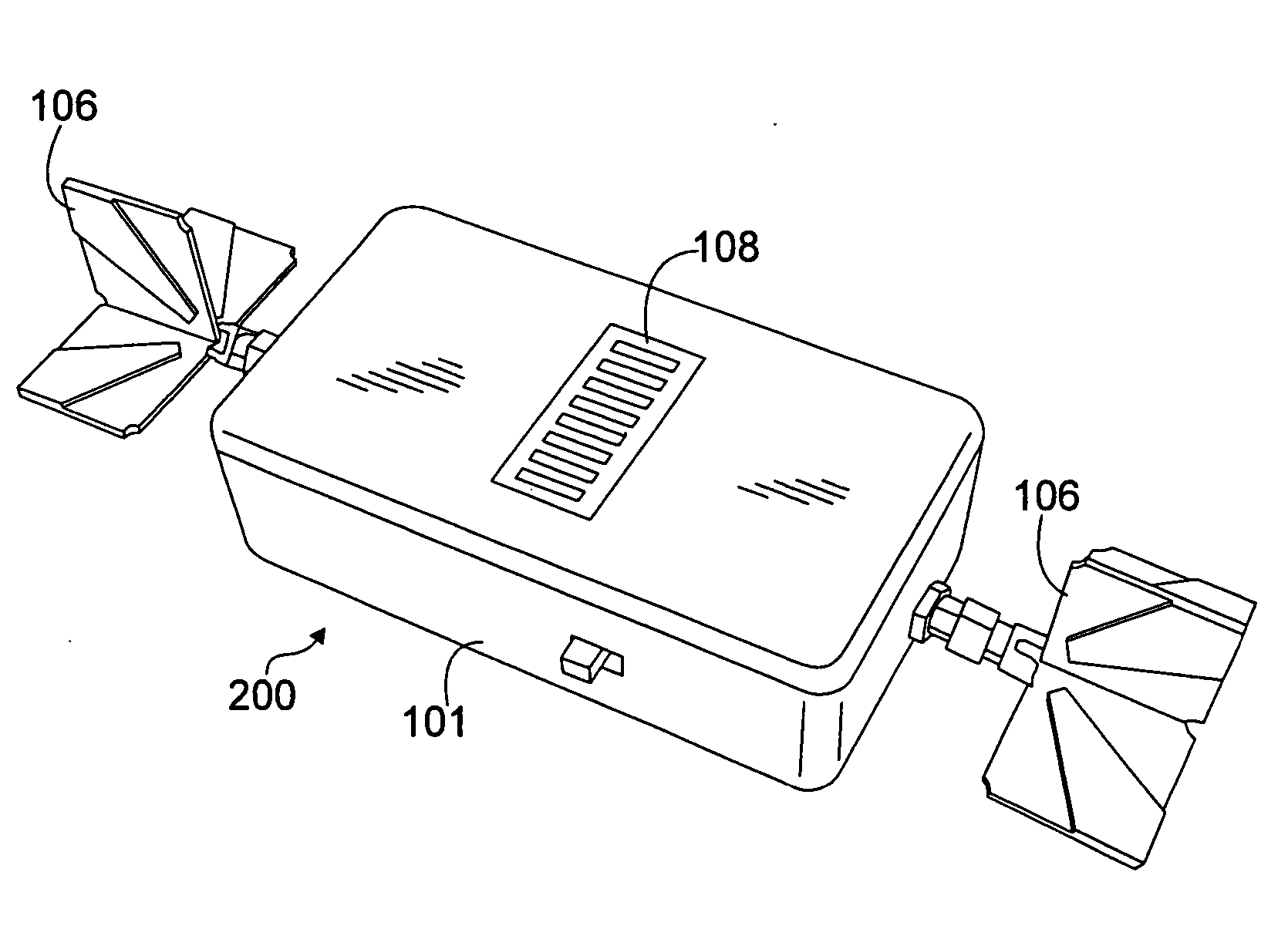
sector antenna / detector units include monopole / detector elements that are co-planar but at angles to each other in their common plane. In an exemplary embodiment, four monopole / detector elements oriented in increments of 90 degrees within their common plane may be used to form the basis of each sector antenna / detector unit. However, the present invention may alternatively employ only three monopole / detector elements oriented at 120 degrees to each other in their common plane within each sector antenna / detector unit and still achieve the desired sensitivity to signals of arbitrary polarization orientation. The co-
planar monopole / detectors are parallel-connected so that sensitivity to signals arriving approximately normal (± at least 45 degrees) to their common plane is achieved regardless of the polarization orientation of the incoming wave.
Wideband directional properties are introduced to the sector antenna / detector unit by placing RF absorber material behind the plane of the monopole / detector elements. The absorber material is backed by
metallic foil which also extends up the sides of the absorber. The relative size of the absorber material and the distance of metallic coverage up the sides are selected to adjust the sector beam-width to approximately 90 degrees.
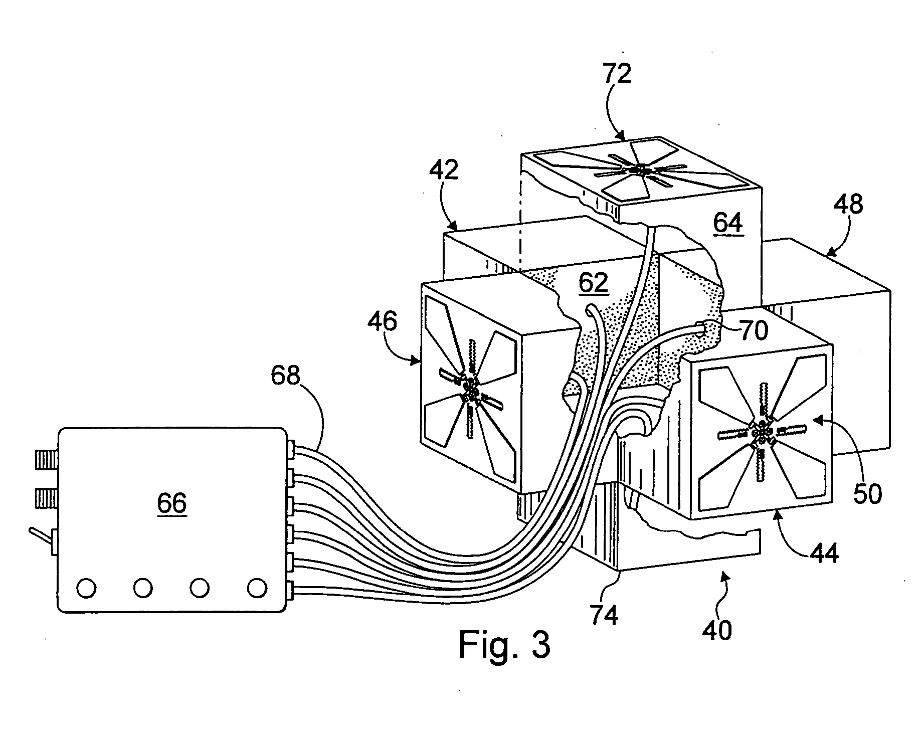
[0034] The present invention also includes an RF generator to field verify that any of the aforementioned detector systems continue to function following some stressful event (e.g., the device is dropped onto a concrete floor). A piezoelectric spark generator creates a
broadband RF spectrum which is applied to an antenna structure which radiates the signal with
frequency response,
directivity and polarization determined by the antenna structure. Generally, a piezoelectric spark generator is mounted in place of the
RF probe that would normally launch RF signals from a
coaxial transmission line into a rectangular
waveguide. Use of an open rectangular
waveguide provides a source for an efficient, directional, linearly polarized emission.

