Method for Gas Storage

a gas storage and gas technology, applied in the field of new, can solve the problems that cannot be explained by macroscopic theory, and achieve the effects of high density of hydrogen storage per surface area, perfect repeatability, and no contamination

Inactive Publication Date: 2008-12-25
SHANGHAI INST OF APPLIED PHYSICS - CHINESE ACAD OF SCI
View PDF5 Cites 9 Cited by
  • Summary
  • Abstract
  • Description
  • Claims
  • Application Information

AI Technical Summary

Benefits of technology

[0008]The object of this invention is to overcome the disadvantage of the prior art and provides a new method for gas storage, particularly a new method for hydrogen storage. This method has perfect repeatability,

Problems solved by technology

But this can not be explai

Method used


Image

  • Method for Gas Storage
  • Method for Gas Storage
  • Method for Gas Storage

Examples


embodiment 1

[0041]As shown in FIG. 5, HOPG 3 in the size of 12 mm×12 mm is used as the facility of hydrogen storage and substrate of AFM observation. HOPG 3 is glued on a matching magnet shim 32 via electric silver epoxy. HOPG 3's surface is freshly cleaved by adhesive tape prior to each experiment. Magnet shim 32 attaching HOPG 3 is absorbed on samples stage of AFM header (not shown in the drawings). AFM tip 31 is loaded to AFM liquid cell 44, the distance between tip 31 and graphite substrate 3 is adjusted to about 40 μm. O-ring is used to seal the space between liquid cell 44 and graphite substrate. This liquid cell 44 also has an drain hole. The diluted sulfuric acid solution of 0.001-10 mol / L 45 pre-degassed is rapidly poured into the liquid cell. Images of the formation of graphite surface detected by AFM before loading a voltage are used as references. Cathode lead 41 is leaded from graphite substrate 3, platinum used as reference electrode 42 is put into electrolytes 45 and anode platin...

embodiment 2

[0049]The device and operation are same as those in embodiment 1. But potassium hydroxide solution of 0.001-10 mol / L is chosen as the electrolyte, the range of voltage loaded is −0.5 V-−2.0 V, the reaction time is at least 0.01 s. Under this condition, the range of height of nanobubbles is 2-100 nm.

[0050]The size of nanobubbles formed in the solution of sodium nitrate, potassium nitrate and barium sulphate etc. with concentration of 0.001-10 mol / L are same as that in the solution of sulfuric acid and potassium hydroxide. Here, we do not illustrate more embodiments about that.

embodiment 3

[0051]Nitrogen nanobubbles are obtained on different solid surfaces by the exchanging of ethanol and water.

[0052]In this invention the exchange of ethanol and water is a method that nanobubbes can be formed on solid surface by replacing gas-saturated ethanol solution in the container with gas-saturated water. Using this method excessive gases can be separated out because of the different solubility between water and ethanol to the same gas. That excessive gas can be absorbed on the surface and form nanobubbles.

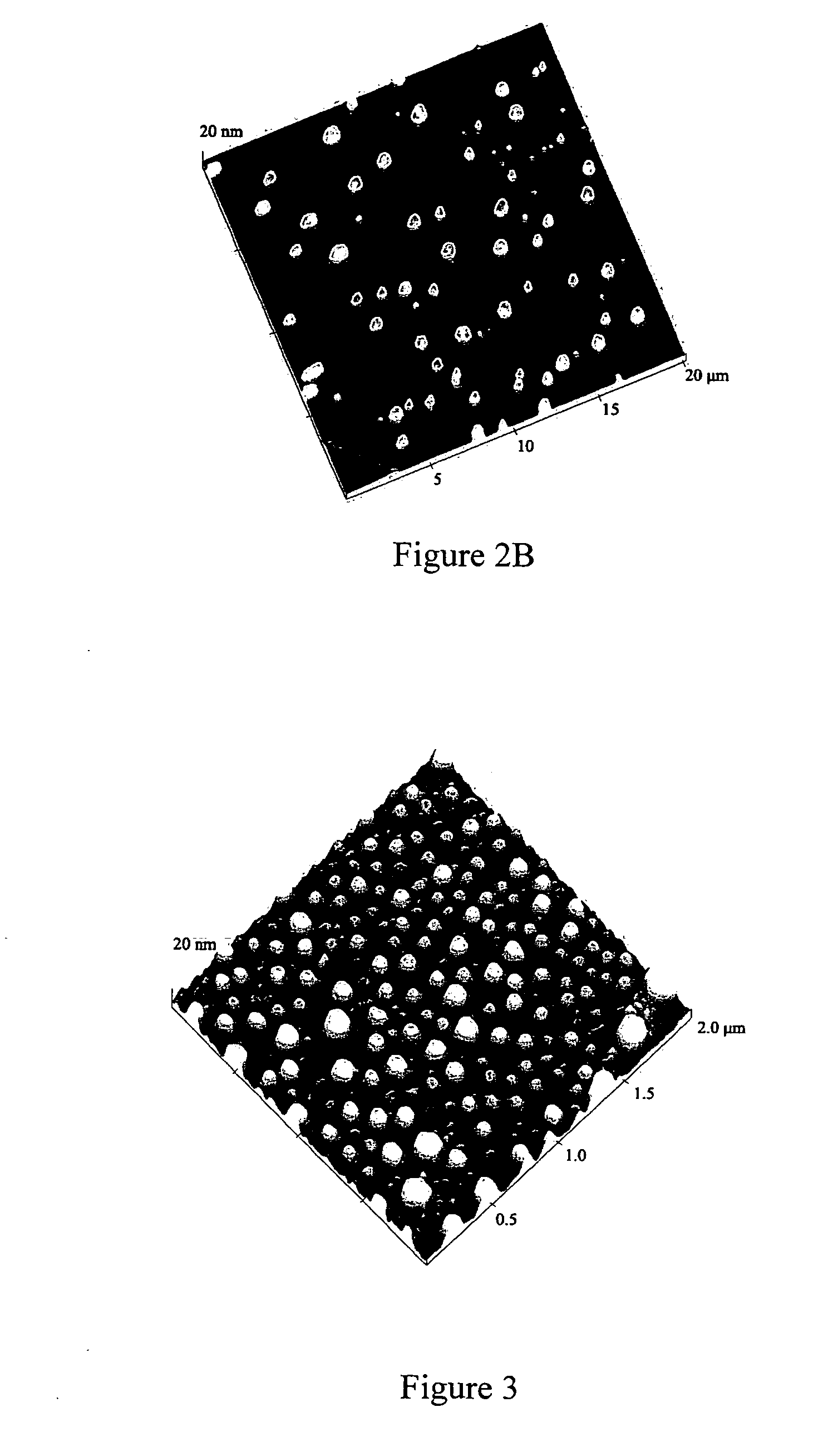
[0053]In this invention water and ethanol is degassed in vacuum pump firstly, then press nitrogen with high pressure into water and ethanol, and water and ethanol are kept in nitrogen saturated state. Nitrogen-saturated ethanol solution is poured into liquid cell quickly, then the solution is replaced by nitrogen-saturated water. The AFM is used to observe. As shown in FIGS. 6A and 6B, the sizes of bubbles absorbed on mica are smaller than that on graphite under the same condi...


PUM


Abstract

This invention released a method for gas storage, characterized that gas is stored in the form of nanometer scale bubbles or gas layers on the solid-liquid surfaces. Said gas is hydrogen, the surface of the solid is planar solid surface, irregular solid surface, or porous material surface, especially highly oriented pyrolytic graphite (HOPG) surface, and the liquid is water, inorganic acid, inorganic salt, inorganic alkali, organic solution or colloid solution. The gas to be stored is produced by electrochemical method, inorganic reaction, organic reaction, biologic reaction or physical method.

Description

FIELDS OF THE INVENTION[0001]This invention relates to a new method for gas storage. Particularly, it refers to a method for gas storage in the form of nanobubbles or nano gas layers on the solid-liquid surface.BACKGROUND OF THE INVENTION[0002]The storage of high purified gas can be used in a lot of fields, especially the storage of hydrogen which is very significant in utilization of hydrogen energy. But recently human being faces a flinty challenge from energy, resource and environmental crisis. This is caused by traditional energy sources, such as petroleum and coal, which become less and less, and greenhouse effects and acid rain produced by conflagrant productions of petroleum and coal, CO2 and SO2. So, human being needs clear and new energy sources. Hydrogen energy attracts much attention from a wide audience of scientists due to reproduction and abundant resources. More importantly, hydrogen does not cause the environmental pollution and is a very ideal and clear energy sourc...

Claims


Application Information

Patent Timeline
IPC IPC(8): C01B3/02
CPCB82Y30/00C01B3/001C01B3/0021Y02E60/325Y02E60/366Y02E60/32Y02E60/36
Inventor ZHANG, LIJUANHU, JUNFANG, HAIPINGFAN, CHUNHAIZHANG, YISHEN, GUANGXLA
Owner SHANGHAI INST OF APPLIED PHYSICS - CHINESE ACAD OF SCI
Why Eureka
Try Eureka