Fluid treatment device having multiple layer honeycomb structure and method of manufacture

a technology of honeycomb and treatment device, which is applied in the direction of machinery/engines, domestic applications, chemical/physical processes, etc., can solve the problems of increasing the amount and hence the cost of precious metals used as catalysts, and the fluid mechanics between a predominantly laminar flow of exhaust gas and the cell walls of a standard honeycomb ceramic structure are not conducive to the efficient achievement of intimate contact, so as to achieve the effect of improving the performance of the devi

Active Publication Date: 2009-02-12
CORNING INC
View PDF17 Cites 33 Cited by
  • Summary
  • Abstract
  • Description
  • Claims
  • Application Information

AI Technical Summary

Benefits of technology

[0008]Generally speaking, the invention is a fluid treatment device particularly adapted for the treatment of exhaust gases that improves the performance of the device. To this end, embodiments of the fluid treatment device of the present invention comprise multiple honeycomb ceramic layers arranged in a stacked configuration between an inlet and outlet. Each ceramic layer includes a matrix of ceramic walls that defines a plurality of parallel, fluid-conducting cells oriented along an axis. In embodiments, each matrix has opposing faces that define inlets and outlets of the cells of that matrix, and a peripheral portion or peripheral region which may or may not include an outer skin. The peripheral portions or peripheral regions of adjacent stacked ceramic layers may be mutually contiguous to prevent fluid, flowing through the ...

Problems solved by technology

Unfortunately, the fluid mechanics between a predominantly laminar flow of exhaust gas and the cell walls of a standard honeycomb ceramic structure are not conducive to the efficient achievement of intimate contact between the catalyst and the poll...

Method used


Image

  • Fluid treatment device having multiple layer honeycomb structure and method of manufacture
  • Fluid treatment device having multiple layer honeycomb structure and method of manufacture
  • Fluid treatment device having multiple layer honeycomb structure and method of manufacture

Examples


example 1

Heat-Up Profiles

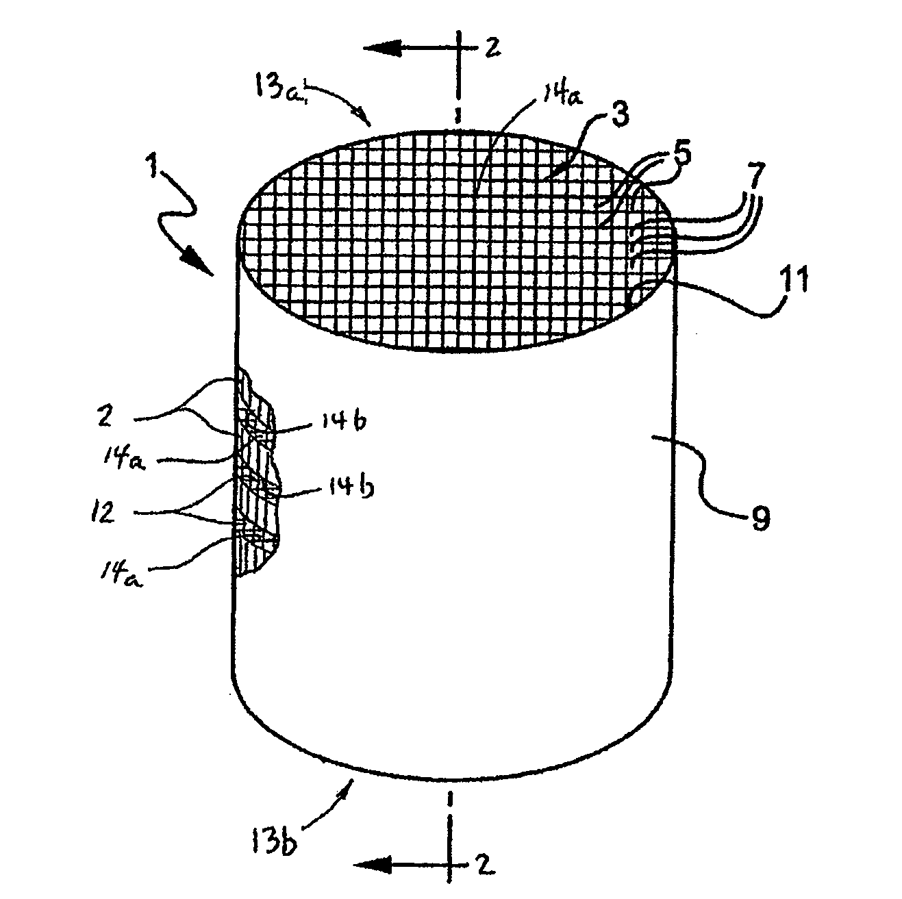
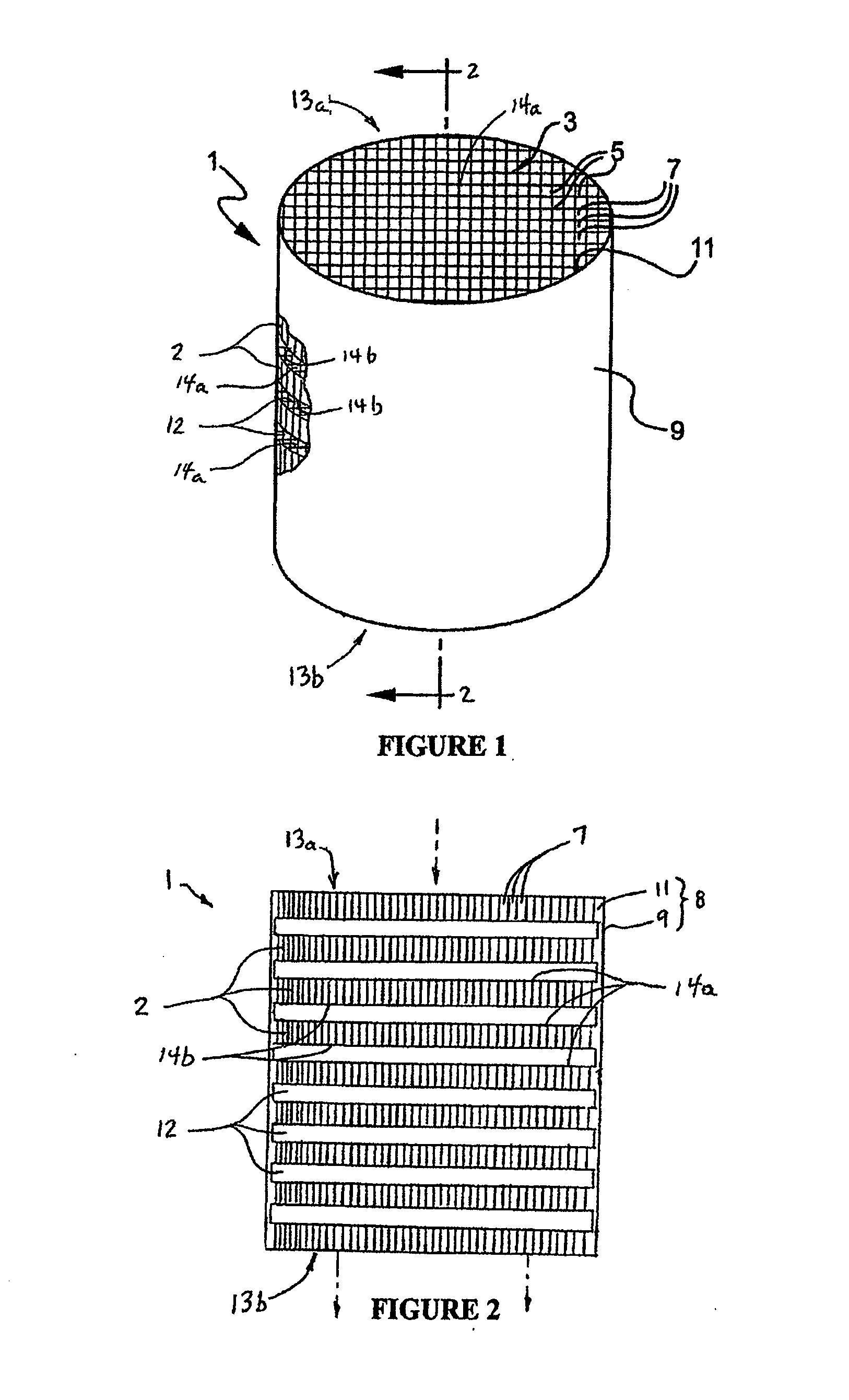
[0067]FIGS. 11A and 11B compare the amount of time required for a standard, continuous matrix ceramic honeycomb structure (FIG. 11A) and a discontinuous cell wall substrate (FIG. 11B) of the invention to obtain a temperature profile across their diameters that would be effective in activating a catalyst for breaking down automotive exhausts. The ceramic honeycomb structure used to obtain the graph of FIG. 11B had a matrix 3 formed from integrally formed, disc-shaped matrix layers 2 separated by axial air spaces 12 as illustrated in FIGS. 1 and 2. The diameter, cell density, web thicknesses and ceramic material 9 (aluminum titanate) of the two structures were identical (4.25 inches in length, 3.66 inches in diameter 600 / 4 substrate), the only difference being that the honeycomb structure embodying the invention shown in FIG. 11B had eight disc-shaped axial spaces in its web matrix 3 that defined axially spaced apart honeycomb layers 2. The temperature profiles were me...

example 2

Radial Thermal Profiles During Heat-Up

[0069]FIG. 12 compares the radial temperature profiles for a prior art, continuous ceramic honeycomb structure and a discontinuous cell wall substrate honeycomb structure embodying the invention having axially spaced-apart, integrally connected layers 2. Because the center of the horizontal axis corresponds to the axis of rotation of these two structures, it is somewhat easier to appreciate the differences in the two thermal profiles. As is the case with comparative FIGS. 11A and 11B, the diameter, cell density, web thicknesses and ceramic material of the two structures were identical, the only difference being that the honeycomb structure embodying the invention had disc-shaped spaces in its matrix 3 that defined eight axially spaced apart honeycomb layers 2. Measurements were taken from thermocouples located 67 mm from the inlet. These graphs clearly indicate that while the center sections of the two structures achieve about the same temperatu...

example 3

Back Pressure Comparisons

[0070]FIG. 13 compares the back pressure, or pressure drop, that a standard and a layered ceramic honeycomb structure, both of which were 3.66 inches in diameter, 4.25 inches in length 600 / 4 substrates, apply to an airflow ranging between 10 and 190 cfm (cubic feet per minute). As can be seen from a comparison of the two graphs, the pressure drop associated with a ceramic honeycomb structure of the invention (where eight, 0.25 inch sections of the web matrix have been removed to define matrix layers) is approximately 10% lower for an airflow of between about 10 and 170 cfm, thus underscoring still another advantage of the invention.


PUM

PropertyMeasurementUnit
Fractionaaaaaaaaaa
Fractionaaaaaaaaaa
Fractionaaaaaaaaaa

Abstract

A device for treating fluids, such as automotive exhaust gases is provided, as well as a method of manufacturing such a device. The invention provides a honeycomb structure, a matrix of ceramic walls that defines a plurality of parallel, fluid-conducting cells oriented along an axis, arranged in a stacked or discontinuous configuration between an inlet and outlet, where adjacent layers of honeycomb structure are separated by layers of air spaces. Each matrix layer has opposing faces that defines the inlets and outlets of the cells, and a peripheral portion or peripheral region including an outer skin. The peripheral portions or peripheral regions of adjacent stacked ceramic layers are mutually contiguous to prevent fluid flowing through the stacked ceramic layers from leaking between said outer skins.

Description

FIELD OF THE INVENTION[0001]This invention generally relates to fluid treatment devices, and is specifically concerned with a multiple layer ceramic honeycomb structure for treating exhaust gases, where the layers of honeycomb structure are separated by air spaces, and methods of making the multiple layer ceramic honeycomb structure.BACKGROUND OF THE INVENTION[0002]Ceramic honeycomb structures are used in vehicular exhaust systems to reduce pollutants. Such structures generally have a network of interconnected walls that form a matrix of elongated, gas-conducting cells which may be square, octagonal or hexagonal in shape. This matrix has been described as a “honeycomb” matrix. For example, the network of walls may be surrounded by a cylindrical outer skin that is integrally connected to the outer edges of the walls to form a cylindrical- or oval-shaped cylindrical structure having opposing inlet and outlet ends for receiving and expelling exhaust gases through the honeycomb matrix o...

Claims


Application Information

Patent Timeline
IPC IPC(8): B01D53/86B01D46/00B29C71/02B01D53/00
CPCB01D46/2451F01N13/0093B01D46/2462B01D46/2466B01D53/9481B01D2046/2492B01D2046/2496B01D2279/30B28B1/002B28B11/12F01N3/0222F01N3/2828F01N2350/06F01N2450/28Y02T10/20F01N13/0097B01D46/2455Y02T10/12B01D46/2486B01D46/2498B01D46/248B01D46/2476
Inventor BERKEY, GEORGE E.HOUSE, KEITH L.
Owner CORNING INC
Why Eureka
Try Eureka