
Microchip For Use In Cytometry, Velocimetry And Cell Sorting Using Polyelectrolytic Salt Bridges

a microchip and cytometry technology, applied in the field of microchips, can solve the problems of affecting the quality of optical parts, the system under study is altered, and the idea has a few serious problems,

Inactive Publication Date: 2009-04-23
SEOUL NAT UNIV R&DB FOUND
View PDF0 Cites 40 Cited by
  • Summary
  • Abstract
  • Description
  • Claims
  • Application Information

AI Technical Summary

Benefits of technology

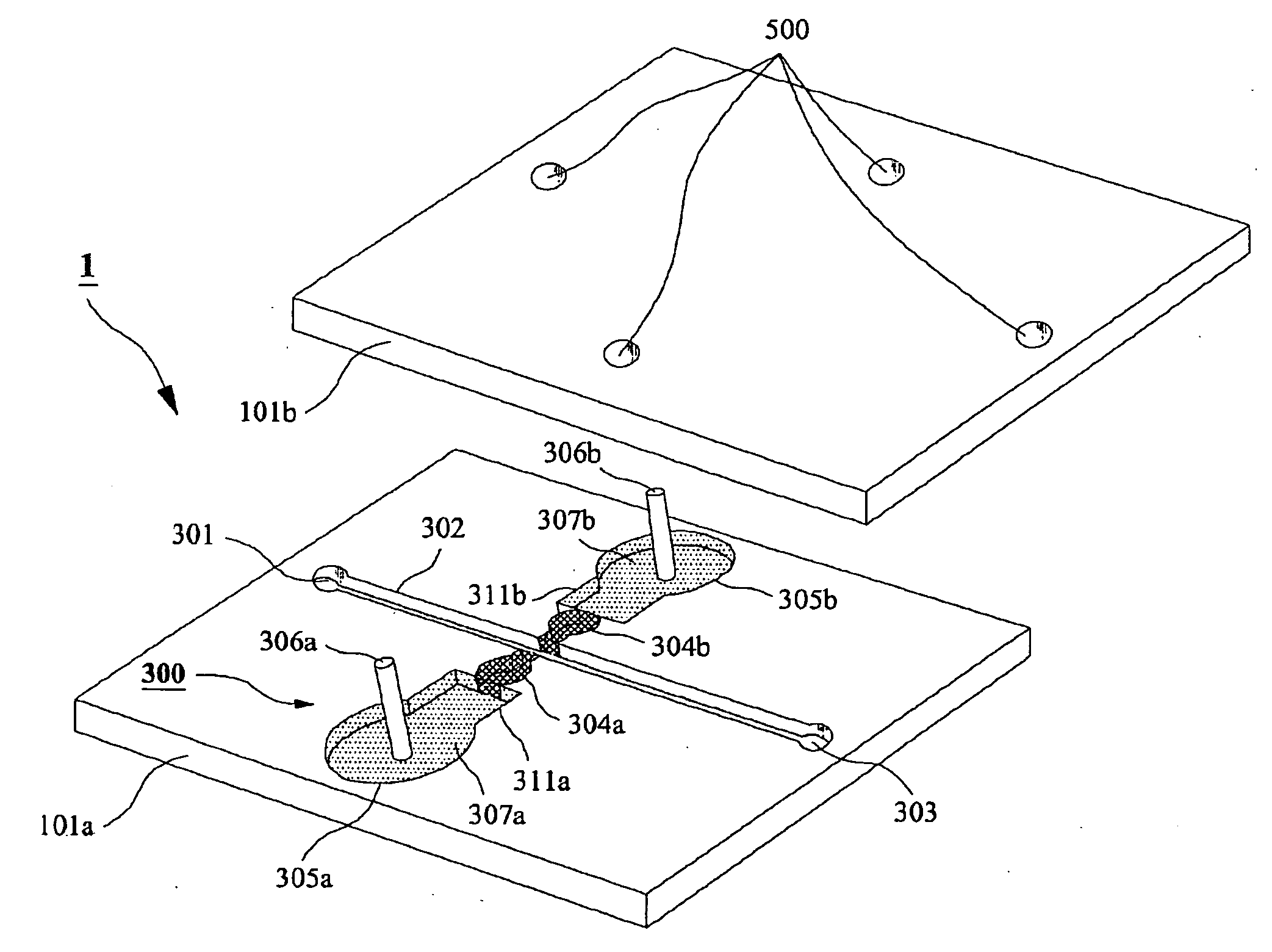
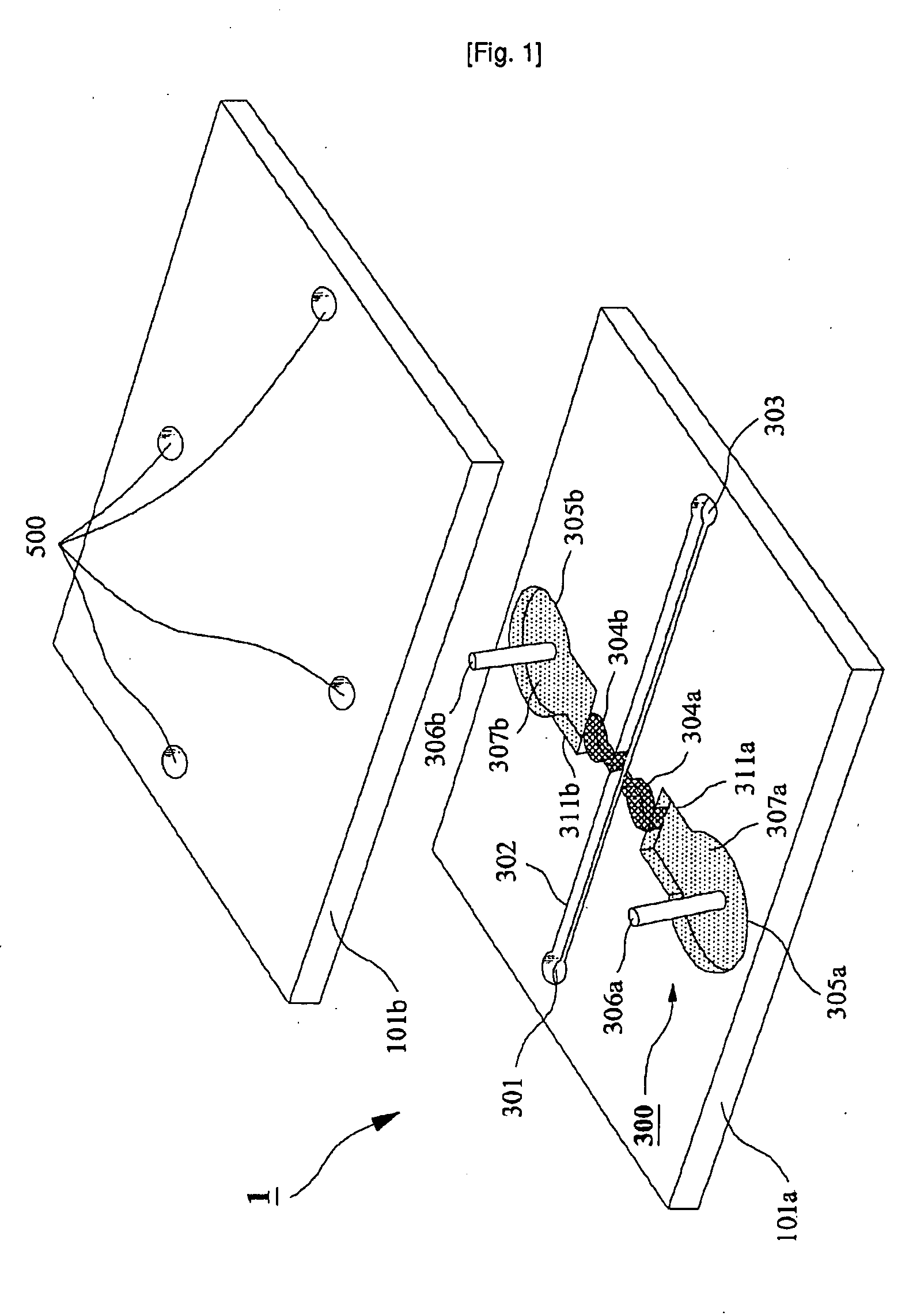
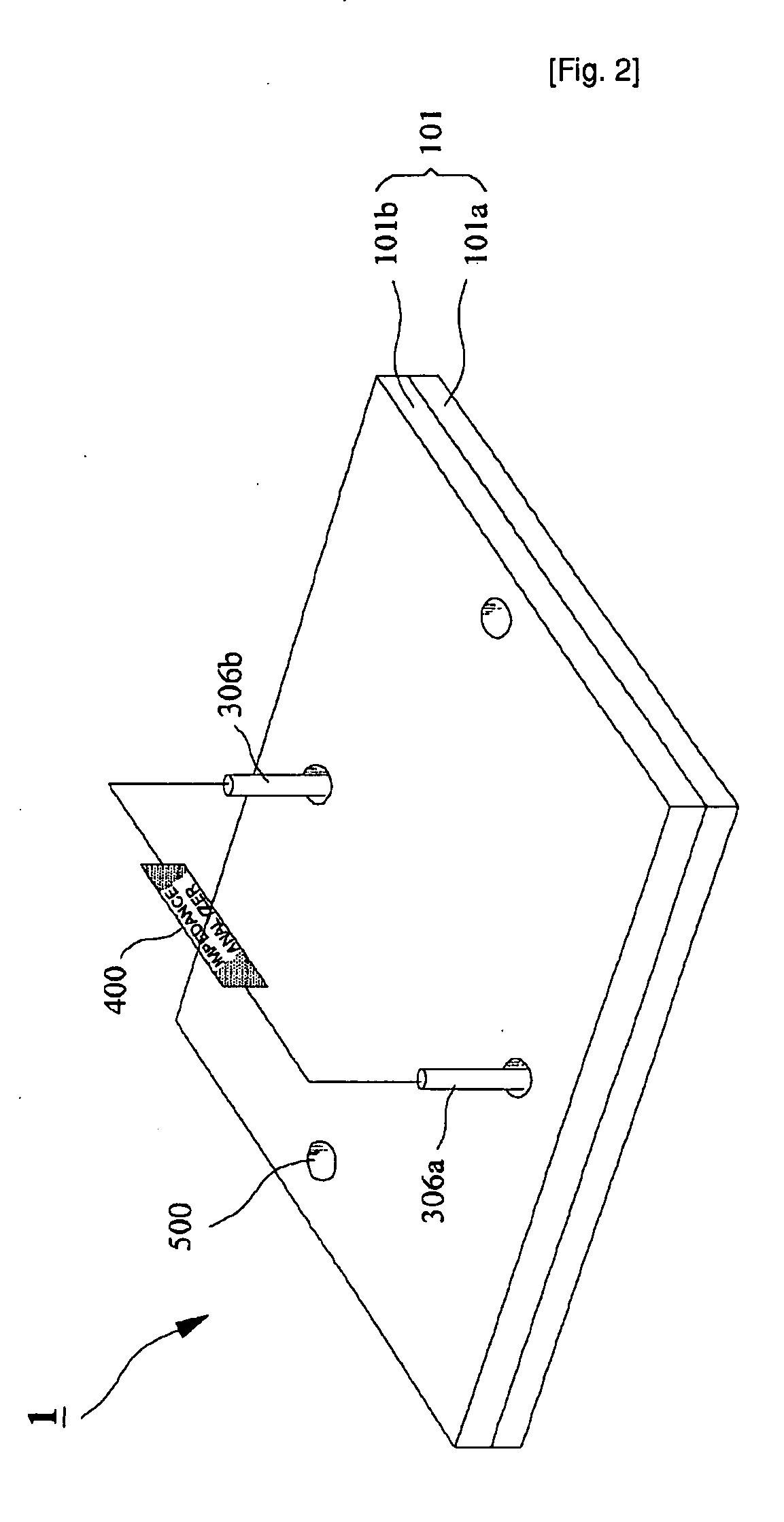
[0008]In order to solve the above-identified disadvantages, there is provided fabrication and performance of a flow cytometric or velocimetric chip using polyelectrolytic salt bridge-based electrode (PSBE). The concept of salt bridge was not so common in microfluidic chip research. Khandurina and co-workers applied porous silicate film as a salt bridge for electrophoresis32. Y. Takamura et al.33 and A. Brask et al.34 developed the low-voltage cascade electro-osmotic pump based on salt bridges. However, polymer-based salt bridge has not been used as an electrode for the detection of moving cells. The PSBE can be easily fabricated at the microchannel walls and make it possible to implement DC impedance analysis. Furthermore, two pairs of the PSBEs separated by a fixed length in a microchannel provide the data revealing the velocity information of cells on the same chip. It is believed that PSBE can offer a new opportunity to accomplish both the size-selective detection and simultaneous velocimetry of cells flowing along a microchannel without large or complex peripheral setup.Technical Solution
[0011]The fabrication technology for PSBE in μTAS was developed and the performance as a flow cytometry glass microchip was also evaluated. It was demonstrated that the developed PSBE could successfully substitute the metal electrode for the impedance analysis in microfluidic glass chip. The PSBEs were embedded on cytometry and velocimetry microchips, which were evaluated using both fluorescent microbeads and human blood cells. Test results show that screening rate over 3,000 samples s−1, measurement of cell velocity up to 100 mm s−1, and velocity-free classification by particle size are possible.

Problems solved by technology

However, this idea has a few serious problems.
Firstly, it requires cell modification by markers or antibodies, which may lead to alteration of the system under study.
Secondly, optical parts can hardly be reduced to the size as small as the microchip itself.
Even if fluidic parts become substantially small by introducing microfluidic technology, the whole system including other parts like the detection unit is still too large to be a practical device for POCT.
Thirdly, the equipments for detection are rather expensive and complex to operate.
Optical equipments are rarely as cheap as electronic devices and necessarily require fine alignment.
But there are fundamental challenges for the electrical method to accomplish such good cytometric functions as the optical detection in FACS offers.
Unfortunately, those trials made only limited success because of the following reasons.
First of all, fabrication of such electrodes was tricky.
Even if those are made somehow, it is hard to guarantee the reproducible geometry and characteristics as electrodes.
Another problem is related to the electrode material and the frequency applied.
However, metal electrodes are not compatible to DC or low frequency of electric potential bias.
Since electric double layer and / or faradaic reaction on the metal electrode surfaces intervenes the circuit, the impedance changes due to the cells become insignificant.
However one dimensional (horizontal) focusing on microfluidic chip cannot produce as good flow as generated in the conventional FACS system.
Thus it is harder to obtain the uniform velocity of the cells on a microfluidic chip.
However, it has limitations in accuracy and cost because the video frame interval obviously regulates its resolution.
Both Shah convolution Fourier transform and AOM methods increase the complexity of instrument and calculation, and have limitations in miniaturization because of the space for the optical system integrated.

Method used


Image

  • Microchip For Use In Cytometry, Velocimetry And Cell Sorting Using Polyelectrolytic Salt Bridges
  • Microchip For Use In Cytometry, Velocimetry And Cell Sorting Using Polyelectrolytic Salt Bridges
  • Microchip For Use In Cytometry, Velocimetry And Cell Sorting Using Polyelectrolytic Salt Bridges

Examples


examples

[0032]Microchip Fabrication

[0033]Corning 2947 precleaned slide glasses (75 mm by 25 mm, 1 mm thick) were used as substrates. A slide glass was cleaned in piranha solution (H2SO4:H2O2=3:1) for 1 h before washing the slide glass with deionized (DI) water (NANOpure Diamond, Barnstead, USA) and cleaned with acetone (CMOS grade, J. T. Baker, USA), methanol (CMOS grade, J. T. Baker, USA) and DI water twice sequentially. The cleaned slide glass was dehydrated on a 150° C. hot plate for 10 min and cooled down to room temperature. In order to modify the surface of the glass substrate, hydrophobic hexa methyl disilazane (HMDS) (Clariant, Switzerland) was spin-coated (Won corporation, Korea) at 4,000 rpm for 30 s on the slide glass, on which spin-coating of the photo resist (PR) of AZ5214-E (Clariant) was followed at 4,000 rpm for 30 s. After soft baking of photo-resist (PR) on a hot plate at 100° C. for 60 s, the slide glass was cooled down to room temperature and aligned under a pattern mask...


PUM


Abstract

The present invention relates to a microchip using polyelectrolyte salt bridge for cytometry, velocimetry, and cell sorting. The microchip comprises; a) an inlet for solution to be analyzed, b) a microchannel which provides a moving passage for solution to be analyzed, c) at least one outlet for solution to be analyzed which has passed through the moving passage, d) at least one electrode system comprising a first and a second salt bridges connected to the microchannel (the two salt bridges face each other), and a first and a second reservoirs connected to said each salt bridge (the reservoir comprises electrode and standard electrolyte solution). The microchip detects analytes in the solution to be analyzed (for example, a cell) by detecting change of impedance. In detail, anion in the standard electrolyte solution, which is comprised in the first reservoir, moves from the first salt bridge to the second salt bridge across the microchannel. Impedance change occurs by interference of anion moving across the microchannel and the change can be detected by impedance analyzer connected to electrodes in the first and the second reservoirs.

Description

TECHNICAL FIELD[0001]The present invention relates to a microchip. More particularly, the present invention relates to a microchip for use in cytometry, velocimetry and cell sorting, comprising polyelectrolytic salt bridges.BACKGROUND ART[0002]The modern concept of micro total analysis systems (μTAS) is dated back to early 1990s when capillary electrophoresis (CE) was developed on a glass chip by Manz et al.1 As previously well-documented, chemical and biological processes on microchip propose appreciable benefits that were unattainable with macro scale process configurations; tiny sample volume for analysis, low cost, easy automation, and high throughput by parallel processing2. Taking these advantages, μTAS keeps expanding its applications to many different areas; clinical diagnostics3,4, single chip Polymerase Chain Reaction (PCR)5,6, DNA separation7,8, DNA sequencing9,10, biological and chemical analysis11-13, cell analysis14-16 and flow cytometry16-27.[0003]Flow cytometry is a ...

Claims


Application Information

Patent Timeline
IPC IPC(8): C12M1/00G01N27/00
CPCB01L3/5027G01N15/1056G01N15/1031G01N15/1023B01L3/502715G01N15/1484B01L2300/0645B01L2200/10B01L2200/0652G01N2015/1486
Inventor KIM, HEE-CHANCHUNG, TAEK DONGCHUN, HONG GU
Owner SEOUL NAT UNIV R&DB FOUND
Learn More