

Solar Cell Having Nanostructure and Method for Preparing the Same
- Summary
- Abstract
- Description
- Claims
- Application Information
AI Technical Summary
Benefits of technology
Problems solved by technology
Method used
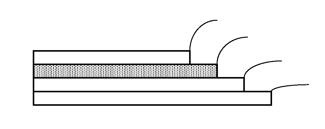
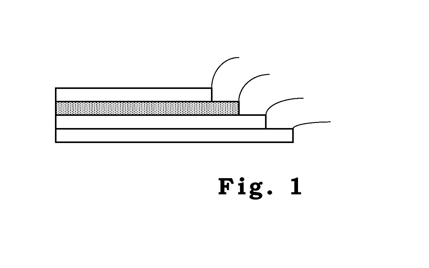
Image

Examples
example 1
Spray Pyrolysis Deposition of TiO2 Hole-Blocking Layer
[0029]The TiO2 compact layer was prepared by spray pyrolysis deposition. Precursor di-isopropoxy titanium bis(acetylacetonate) [Ti(acac)2(i-C3H7O)2] was synthesized in an inert gas atmosphere by the dropwise addition of acetylacetone to a stirred solution of [Ti(i-C3H7O)4] (molar ratio 2:1). A solution of [Ti(acac)2(i-C3H7O)2+2 i-C3H7OH] (TAA) was thus formed and stored in an atmosphere of nitrogen prior to use. 2 M of TAA solution was diluted with ethanol to 0.2 M immediately before each coating process. The aerosol was prepared using a chromatographic atomizer. Before spraying, the handheld device was directed onto the sample, and the distance between the sample and the atomizer was maintained at 19-20 cm. Thin films of TiO2 were prepared using a particular number of repetitions of single spraying steps. A surface of 25.0 mm×10.0 mm in most cases underwent one spraying step, followed by a 30s break before subsequent spraying. T...
example 2
Preparation and Sintering of Nanoporous TiO2 Film
[0030]Titanium isopropoxide, 2-propanol and nitric acid were purchased from Acros and used without further purification. TiO2 colloid dispersions were prepared by the sol-gel reaction of titanium isopropoxide, Ti(OCH(CH3)2)4, as follows. Under a stream of dry nitrogen, 25 mL of Ti(OCH(CH3)2)4 was added via a drooping funnel to 4 mL of 2-propanol. The mixture was added to 150 mL of deionized water over 10 min with vigorous stirring. Within 10 min of the addition of alkoxide, 1.14 mL of 65% nitric acid was further added to the system. The reaction was continued for 8 h at 80° C. The resulting sol was then concentrated in a vacuum at room temperature until the TiO2 concentration was about 80 gL−1. Finally, two drops of nonionic surfactant, Triton-X 100, were added to the solution and the solution was then stirred for several hours to enhance the colloidal stability and size uniformity of TiO2.
[0031]Nanocrystalline TiO2 was deposited on t...
example 3-1
Electropolymerization of Bithiophene into Nanoporous Titania Films
[0032]Polybithiophene(PBiTh) was electrodeposited on the TiO2 matrix using a three-electrode cell configuration. The working electrode was FTO glass coated with the compact and porous TiO2 film, while Pt mesh and Ag / AgCl served as the counter electrode and reference electrode, respectively. PBiTh was electrodeposited in a mixed solution of 0.02 M 2,2′-bithiophene (Aldrich, 97%) and 0.01 M HClO4 water / acetonitrile with a volume ratio of 1:1. The amount of polymer deposited on the working electrode was controlled by monitoring the total amount of charge consumed by the reaction, and the precipitated charge was maintained at 15 mC / cm2. After the electrochemical preparation, the films were carefully rinsed with pure acetonitrile and washed by distilled water to remove any monomer residues. Then, the polymer film was cycled through a cathodic step of −0.4 V in monomer-free water / acetonitrile solution until the current was ...
PUM
| Property | Measurement | Unit |
|---|---|---|
| Structure | aaaaa | aaaaa |
| Electric charge | aaaaa | aaaaa |
| Pore | aaaaa | aaaaa |
Abstract
Description
Claims
Application Information