

High performance coatings and surfaces to mitigate corrosion and fouling in fired heater tubes
a technology of high-performance coatings and surfaces, applied in the direction of muffling furnaces, furnaces, lighting and heating apparatus, etc., can solve the problems of reducing heating efficiency, limiting residence time, coke formation and accumulation on visbreaker walls, etc., to reduce the risk of sulfidation and other forms of high-temperature corrosion, suppress fouling, and reduce the effect of carburization
- Summary
- Abstract
- Description
- Claims
- Application Information
AI Technical Summary
Benefits of technology
Problems solved by technology
Method used
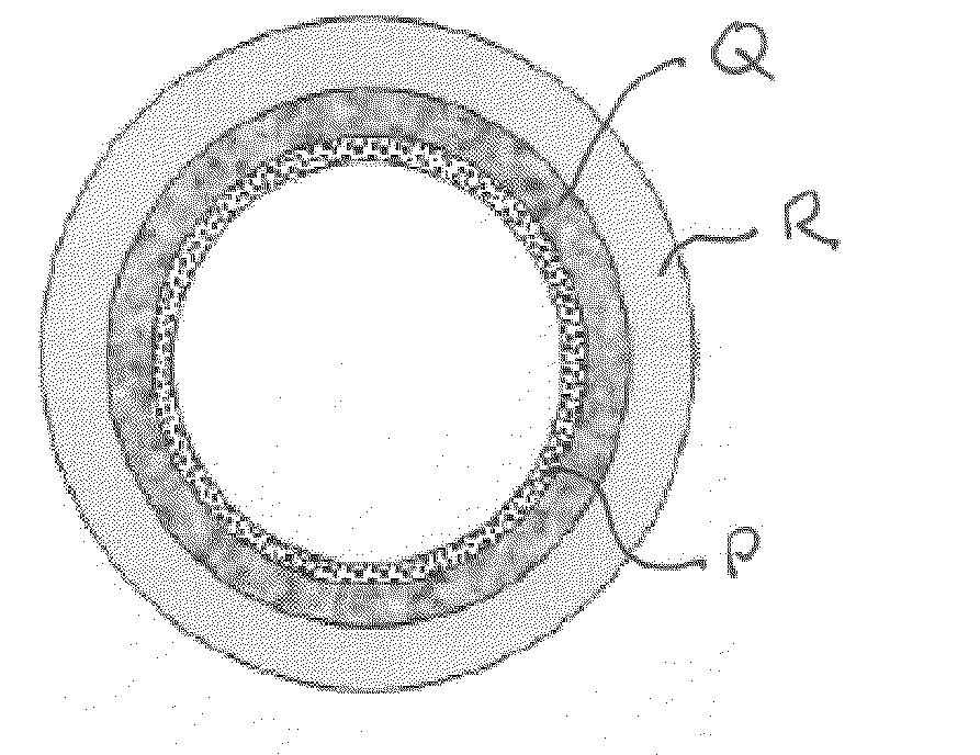
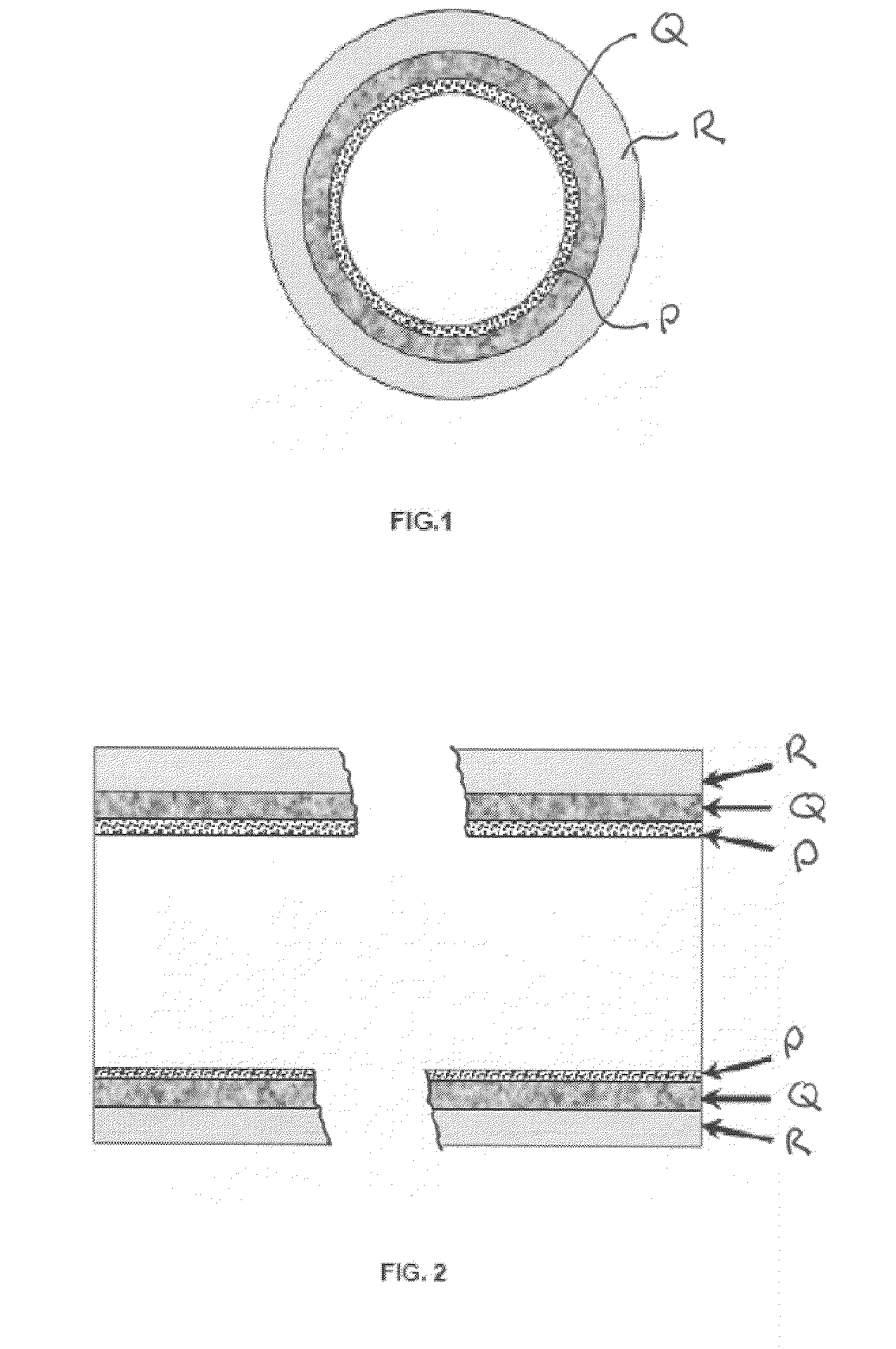
Image

Examples
example 1
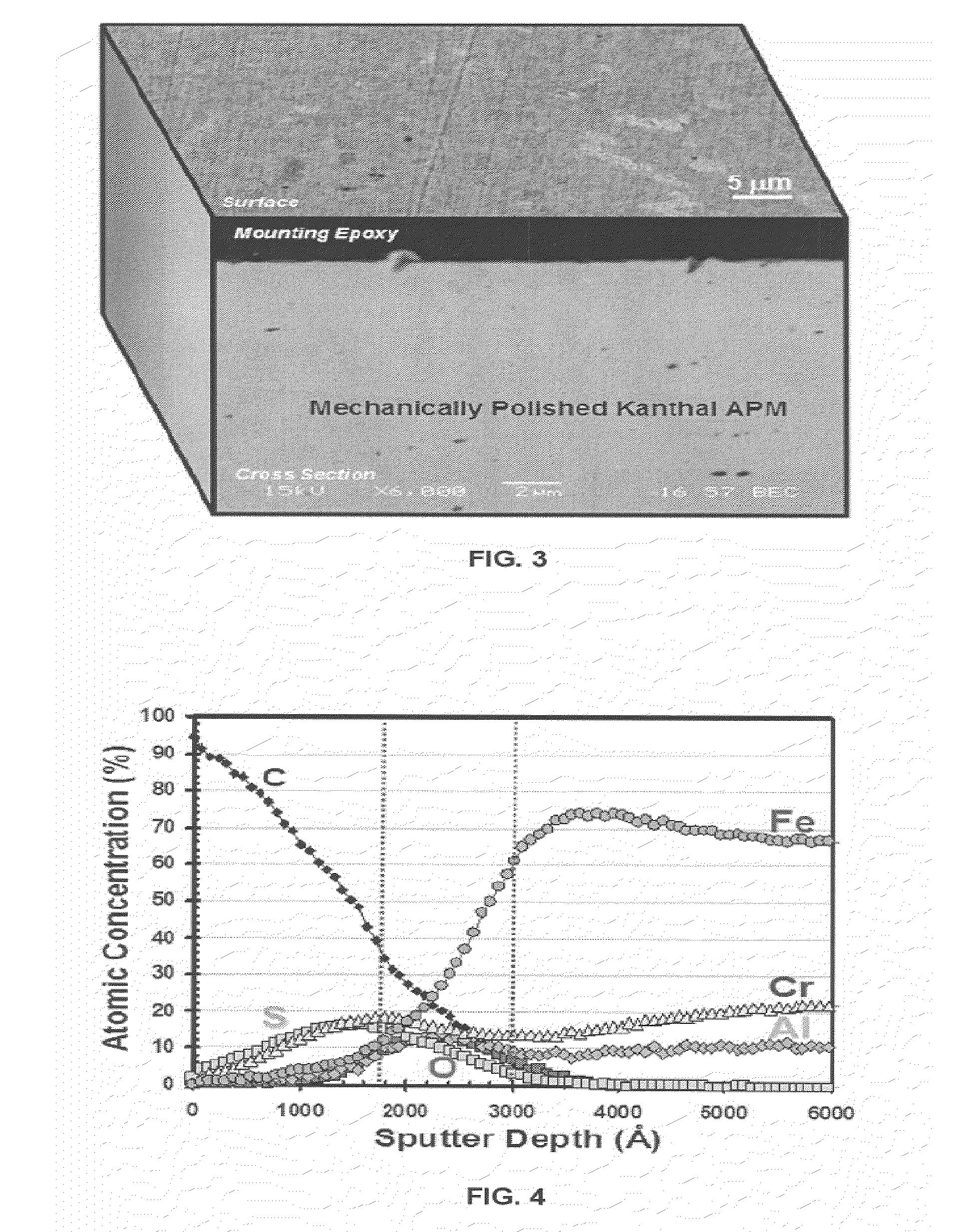
[0050]Following the test methods described above, a mechanically polished Kanthal APM sample was tested. FIG. 3 depicts surface and cross-sectional SEM images of the corrosion surface of a mechanically polished Kanthal APM after reaction at 1000° F. (538° C.) in heavy resid-content crude for 4 hours. No significant corrosion or fouling deposits were observed after the specimen was cleaned in toluene and acetone sequentially. FIG. 4 depicts AES concentration depth profile of the corrosion surface of the same sample. The carbon peak found near the surface was probably caused by remnants of crude deposits. Also identified was about 200 nm thick corrosion scale, which was mainly comprised of Cr—Fe sulfide and Cr—Al oxide. Under this layer, about 200 nm thick alumina sublayer formation was observed. This alumina layer provides superior corrosion resistance of the coating metal, which is prerequisite for fouling mitigation.
example 2
[0051]Following the test methods described above, a 120 grit finished Kanthal APM sample was tested. FIG. 5 depicts surface and cross-sectional SEM images of the corrosion surface of a 120 grit finished Kanthal APM after reaction at 1000° F. (538° C.) in heavy resid-content crude for 4 hours. After cleaned the specimen in in toluene and acetone sequentially, no significant corrosion scale was observed. However, some thin layer of carbon deposit was observed on the surface, whose deposit appeared to be anchored to the roughened surface of the metal. Superior corrosion resistance was attributed to alumina layer formed on the metal surface. The thickness of alumina layer was about 200 nm measured by AES.
[0052]The cross-section SEM images illustrated in FIGS. 3 and 5 illustrate the effect of surface roughness in reduction of carbon deposit. Two samples were tested and cleaned at the same experimental conditions. The thickness of the carbon deposit on the rough surface (e.g. 120 grit fin...
example 5
NiFeCrAl-5 on 347 Stainless Steel
[0056]A coating metal (NiFeCrAl-5 in Table 1, Ba1.Ni:21.6Cr:5.5Al:34.9Fe:0.3Si) was formed a 347 stainless steel base metal surface by a PPW method. The tubular base metal had a size of 95.25 mm OD×5.72 mm WT×10 cm length. About 2.4 mm thick coating metal was applied to a base metal and machined to about 1.5 mm thickness with the average surface roughness of about 40 micro inches. Following the test method described above, the NiFeCrAl-5 coated 347SS specimen was tested at 1056 F (560 C) for 20 hours in a heavy resid medium. No corrosion was observed on the NiFeCrAl-5 coating metal surface after the specimen was retrieved from a reactor. About 100 nm thick protective oxide (alumina) layer was identified on the surface of the PPW coating metal. This alumina layer provided superior corrosion resistance.
[0057]Example 6
NiFeCr on 347 Stainless Steel
[0058]A coating metal (NiFeCr in Table 1, Ba1.Ni:44.6Cr:8.9Fe:0.3Si) was formed on a 347 stainless steel bas...
PUM
| Property | Measurement | Unit |
|---|---|---|
| thickness | aaaaa | aaaaa |
| thickness | aaaaa | aaaaa |
| thickness | aaaaa | aaaaa |
Abstract
Description
Claims
Application Information