Fabrication of tissue lamina using microfabricated two-dimensional molds

a two-dimensional mold and tissue technology, applied in the field of tissue engineering, can solve the problems of countless patients suffering, the severe shortage of donor organs available to these patients remains the crux of the problem, and the organ shortage has become critical and continues to worsen

Inactive Publication Date: 2010-04-22
THE GENERAL HOSPITAL CORP +1
View PDF73 Cites 38 Cited by
  • Summary
  • Abstract
  • Description
  • Claims
  • Application Information

AI Technical Summary

Benefits of technology

[0031]The tissue can be systematically folded or rolled and compacted into a three-dimensional vascularized structure. This structure can be implanted into animals or patients by directly connecting the blood vessels. Optionally, the semi-permeable membrane can be removed. Immediate perfusion of oxygenated blood occurs, which allows survival and function of the entire living mass.

Problems solved by technology

Vital organ failure is one of the most critical problems facing the health care field today.
However, the shortage of organs needed for transplantation has become critical and continues to worsen.
Despite advances in living donor organ transplantation, a severe shortage of donor organs available to these patients remains as the crux of the problem.
Therefore, countless patients suffer as a result.
However, due to the intrinsic limitations of these technologies, these approaches are only partial solutions to the problem.
Tissue engineering can be a complete and permanent solution to the problem of organ loss or failure, but the primary challenge for tissue engineering vital organs is the requirement for a vascular supply for nutrient and metabolite transfer.
However, the relatively long time course for angiogenesis limits the size of the newly formed tissue.
However, this approach is essentially a two-dimensional technology and it is unknown whether it can be adapted to the generation of thick, three-dimensional tissues.
However, this technique is limited by the characteristics and chemistry of the particular polymers.
Also, it severely limits the types of tissue to be fabricated.
For example, these polymer walls do not allow the plasma exchange that is needed in the alveolar capillary wall of the lung.
A further limitation of the prior art methods of tissue engineering is related to mass transport.
Tissue engineered constructs without a blood supply develop hypoxia and nutrient deprivation.
This strategy has worked well for many tissues; however, it falls short for thick, complex tissues such as large vital organs, including liver, kidney, and heart.

Method used


Image

  • Fabrication of tissue lamina  using microfabricated two-dimensional molds
  • Fabrication of tissue lamina  using microfabricated two-dimensional molds
  • Fabrication of tissue lamina  using microfabricated two-dimensional molds

Examples


example 1

Micromaching of Template to tissue engineer Branched Vascularized Channels for Liver Fabrication

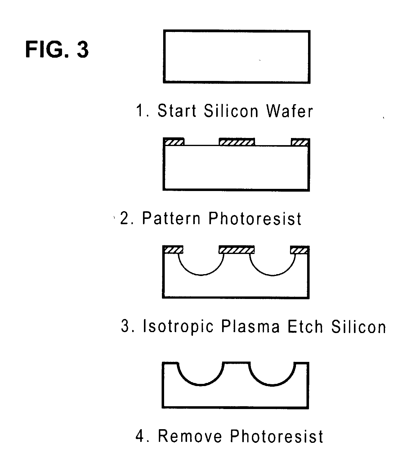
[0168]Micromachining technologies were used on silicon and pyrex surfaces to generate complete vascular systems that can be integrated with engineered tissue before implantation. Trench patterns reminiscent of branched architecture of vascular and capillary networks were etched using standard photolithographic techniques onto silicon and pyrex surfaces to serve as templates. Hepatocytes and endothelial cells were cultured and subsequently lifted as single-cell monolayers from these two dimensional molds. Both cell types were viable and proliferative on these surfaces. In addition, hepatocytes maintained albumin production. The lifted monolayers were then folded into compact three-dimensional tissues. The goal is to lift these branched vascular networks from two-dimensional templates so that they can be combined with layers of parenchymal tissue, such as hepatocytes, to form three-dimensio...

example 2

Endothelialized Microvascular Networks Grown on Micromachined Pyrex® Templates for Tissue Engineering of Vital Organs

[0211]This Example shows the design, modeling, and experimental / computational testing of the endothelialized microvascular matrices grown on micromachined Pyrex® templates. Patterns of microvascular networks were etched using microfabrication technologies on Pyrex® wafers. The pattern consisted of 10 generations of bifurcations from a single inflow channel of width 3 mm down to channels of width of 30 μm.

[0212]The channels were then collected to a single outflow. All channels were etched to the same depth of 30 μm. The Pyrex® wafer was sealed to a flat silicone rubber sheet of the same size. Endothelial cells harvested from rat lung were successfully seeded and expanded under continuous flow conditions in this microvascular network. Red blood cells harvested from rat were heparinized and perfused into the endothelialized channels, and successfully collected at the out...

example 3

Microfluidics Device for Tissue Engineering Microvasculature

Endothelial Cell Culture

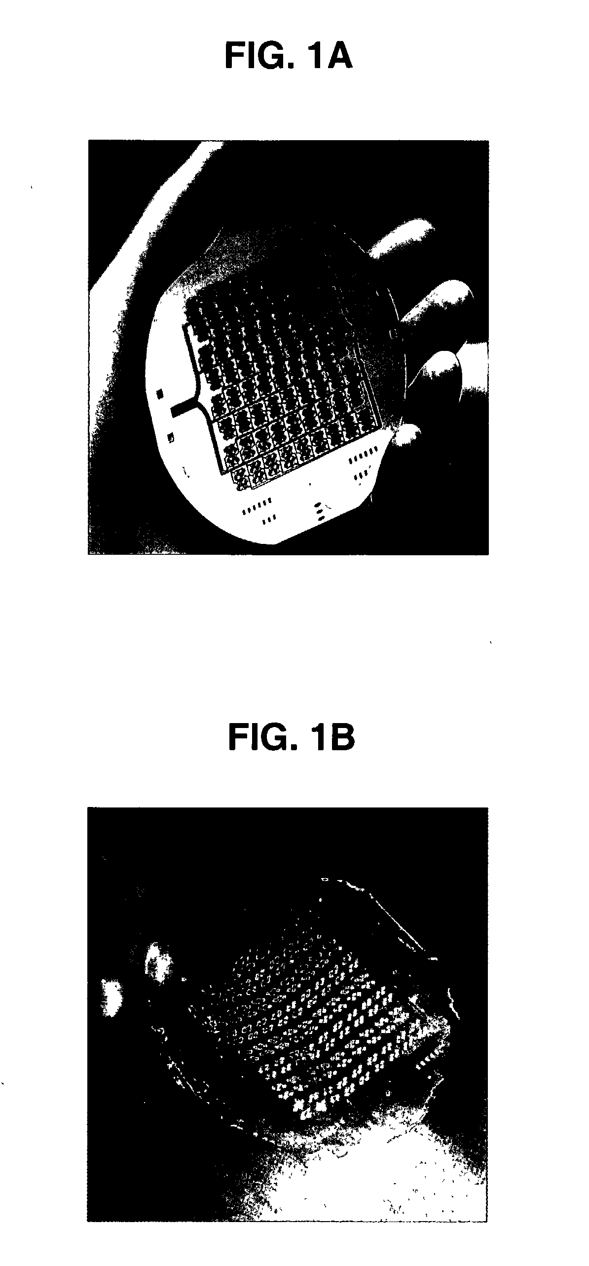
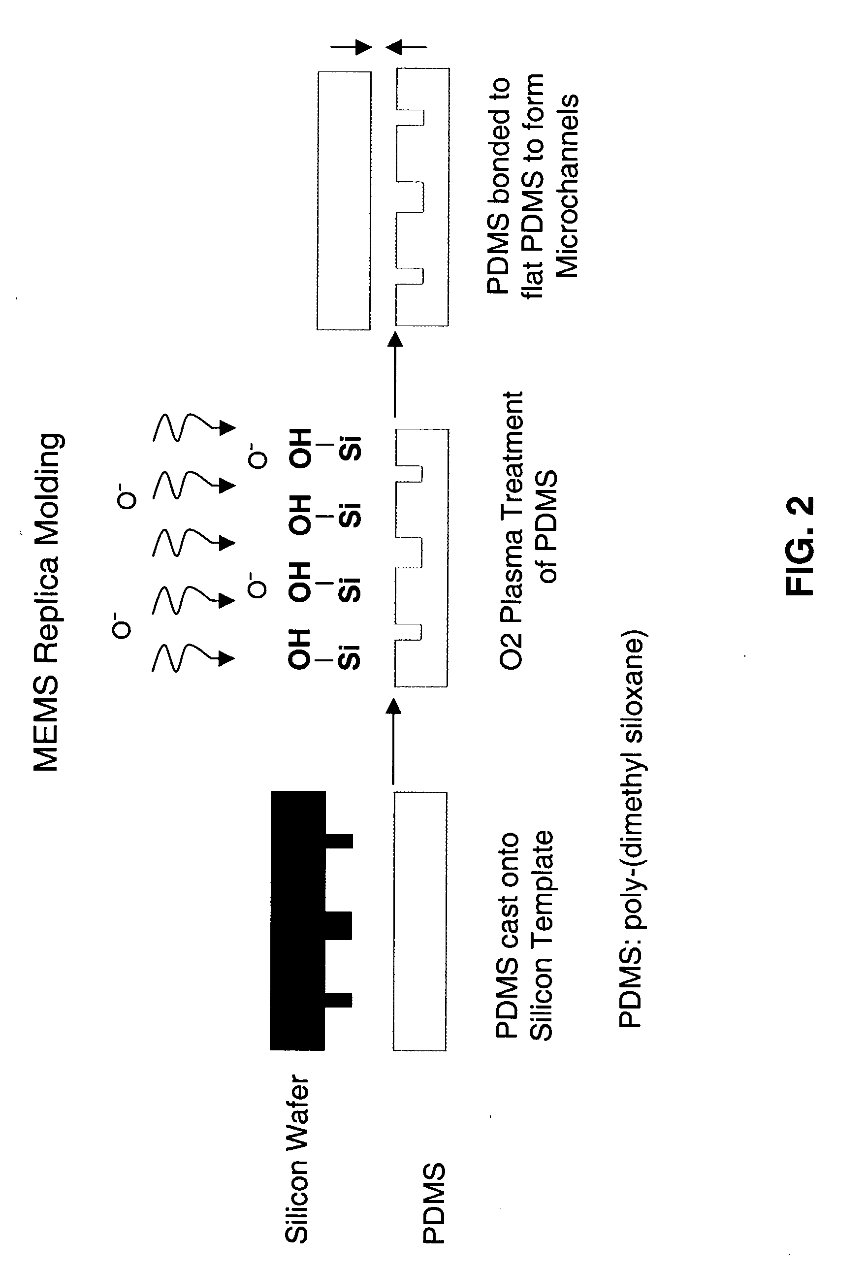
[0216]In this Example, the fabrication of the microfluidic mold, in vitro seeding, and extended cell culture in the mold is demonstrated. Capillary networks were fabricated in biocompatible PDMS, sterilized, coated with cell adhesion molecules, and seeded with cells. Cell-containing molds were then connected to a closed-loop bioreactor for long-term culture. Continuous-flow culture of endothelial cells for up to 4 weeks without occlusion or contamination was achieved.

[0217]Traditional soft lithography microfluidics were used as a prototype matrix. These cell-containing microfluidics are capable of supporting long-term culture in vitro, because in vitro expansion of cells prior to implantation can take several weeks. The prototype matrix is designed to supply sufficient oxygen and nutrients and to remove excretory products while avoiding large shear stresses. The matrix is useful for long-term microfl...


PUM

PropertyMeasurementUnit
diameteraaaaaaaaaa
lengthaaaaaaaaaa
lengthaaaaaaaaaa

Abstract

Methods and materials for making complex, living, vascularized tissues for organ and tissue replacement, especially complex and / or thick structures, such as liver tissue is provided. Tissue lamina is made in a system comprising an apparatus having (a) a first mold or polymer scaffold, a semi-permeable membrane, and a second mold or polymer scaffold, wherein the semi-permeable membrane is disposed between the first and second molds or polymer scaffolds, wherein the first and second molds or polymer scaffolds have means defining microchannels positioned toward the semi-permeable membrane, wherein the first and second molds or polymer scaffolds are fastened together; and (b) animal cells. Methods for producing complex, three-dimensional tissues or organs from tissue lamina are also provided.

Description

RELATED APPLICATIONS[0001]This application is a CIP of U.S. Ser. No. 09 / 560,480, filed Apr. 28, 2000, which claims priority to U.S. Ser. No. 60 / 131,930 filed Apr. 30, 1999, and U.S. Ser. No. 60 / 165,329, filed Nov. 12, 1999. This application also claims priority to U.S. Ser. No. 60 / 367,675, filed Mar. 25, 2002, and to U.S. Ser. No. 10 / 038,891, filed Jan. 2, 2002, which claims priority to U.S. Ser. No. 60 / 259,283, filed Jan. 2, 2001.[0002]Each of the foregoing applications and patents and articles, and each document cited or referenced in each of the foregoing applications and patents and articles, including during the prosecution of each of the foregoing applications and patents (“application and article cited documents”), and any manufacturer's instructions or catalogues for any products cited or mentioned in each of the foregoing applications and patents and articles and in any of the application and article cited documents, are hereby incorporated herein by reference. Furthermore,...

Claims


Application Information

Patent Timeline
Patent Type & Authority Applications(United States)
IPC IPC(8): A61K35/00A61K9/00A61K35/32A61K35/34A61L27/38B22C9/22C12M3/04C12N5/00C12N5/071
CPCA61L27/3604A61L27/3804C12N5/0062Y10T29/49826C12N2533/12C12N2533/30C12M21/08C12N5/0697C12M23/06C12M23/30C12M25/02C12M35/08B33Y80/00A61F2240/004A61F2240/005A61F2/062A61L27/3808A61L27/3891A61L27/3895A61L27/58A61L2300/64
Inventor VACANTI, JOSEPH P.SHIN, YOUNG-MOON MICHAELOGILVIE, JENNIFERSEVY, ALEXANDERMAEMURA, TOMOYUKIISHII, OSAMUKAAZEMPUR-MOFRAD, MOHAMMAD REZABORENSTEIN, JEFFREY T.KING, KEVIN R.WANG, CHIAO-CHUNWEINBERG, ELI
Owner THE GENERAL HOSPITAL CORP
Why Eureka
Try Eureka