
Drying and gasification process

a gasification process and gasification technology, applied in the field of gasification process, can solve the problems of large and more expensive boiler plants, large volume of boilers, and inability to make a wide spread difference in the local or global energy market of biomass, and achieve the effect of reducing the surface moisture content of carbonaceous substances

Inactive Publication Date: 2010-05-13
CORK DAVID
View PDF7 Cites 18 Cited by
  • Summary
  • Abstract
  • Description
  • Claims
  • Application Information

AI Technical Summary

Benefits of technology

[0026]b) reducing the inherent moisture of the carbonaceous substance; and,
[0028]According to one embodiment at step a) the hot gas is a waste gas from a combustion process, or, the hot gas is indirectly heated by waste heat before contacting the carbonaceous substance. Preferably, the carbonaceous substance is at least partially fluidised when contacted with the hot gas and the temperature of the carbonaceous substance is between 25° C. and 100° C. after step a) and before step b) and the surface moisture content of the carbonaceous substance is reduced compared to the its surface moisture content prior to step a).

Problems solved by technology

However, biomass has failed to make a wide spread difference to the local or global energy market for two reasons:1. Biomass typically has a very high moisture content of 30 to 80%.
This usually results in a larger and more expensive boiler plant and lower conversion efficiency of thermal to electrical energy.2. Biomass is distributed across large areas of land, making collection and transport to a central power station prohibitively expensive.
Nevertheless, inefficient open cycle power generation is widely practiced in Queensland using sugar cane bagasse and in Scandinavia using wood waste.
These open cycle power plants tend to be over 5 MWe in size as steam turbines do not scale down in size economically.
In areas where biomass availability is less, which is most of the world, 5MWe is too big for a viable biomass power station that uses open cycle power generation.
Unfortunately, the down draft char gas system does not accept a wide range of biomass and the wood or char that they do accept must be carefully sized and dry.
Fluidised bed gasifiers accept a large range of biomasses and have a wide size distribution but are traditionally unacceptable for use with reciprocating internal combustion engines due to excessive tar carryover.
Unfortunately these biomasses emit ammonia at temperatures near 100° C. and sulphurous compounds, like H2S and COS, between 150 and 300° C. In addition, the waste from poultry sheds often includes dead chickens which could also be used as a biomass fuel source, however these give off hydrogen cyanide when heated to temperatures around 300° C.
Unfortunately, the biomass from these activities tends to be of low quality due to very high moisture content compared to wood.
Tea tree oil biomass has similar problems.
The difficulty with low rank coals, such as brown and sub-bituminous coals is their high moisture content which typically results in a larger and more expensive boiler plant and lower conversion efficiencies.
The main disadvantage with HRL's IDGCC process, with respect to biomass, is the cost associated with building a vertical fluidised bed gasifier that can operate at elevated temperatures above 950° C. and at pressures exceeding 10 atmospheres and doing so for a plant as small as 0.5 to 5 MWe.
The HRL design cannot separate ammonia and sulphurous compounds from the exhaust gas and all these undesirable gases pass through to the turbine.
However, it is a problem with gas engines where the gas is burnt inside the engine.
This idea has not been commercialised due to the poor heat transfer between the steam tubes and the coal.
However when one considers the possible feed stocks of manure and municipal solid waste with their high sulphur, ammonia and halogen loading a single step dryer loses appeal.
In fact it becomes undesirable to return the drier's exhaust to the pyrolyser.
Therefore the Viking gasifier is limited to relatively clean wood waste.
Also the Viking gasifer has low syn-gas CV leading to higher capital cost per KW at the gas engine and low power output for the plants size.

Method used


Image

  • Drying and gasification process
  • Drying and gasification process
  • Drying and gasification process

Examples


example 1

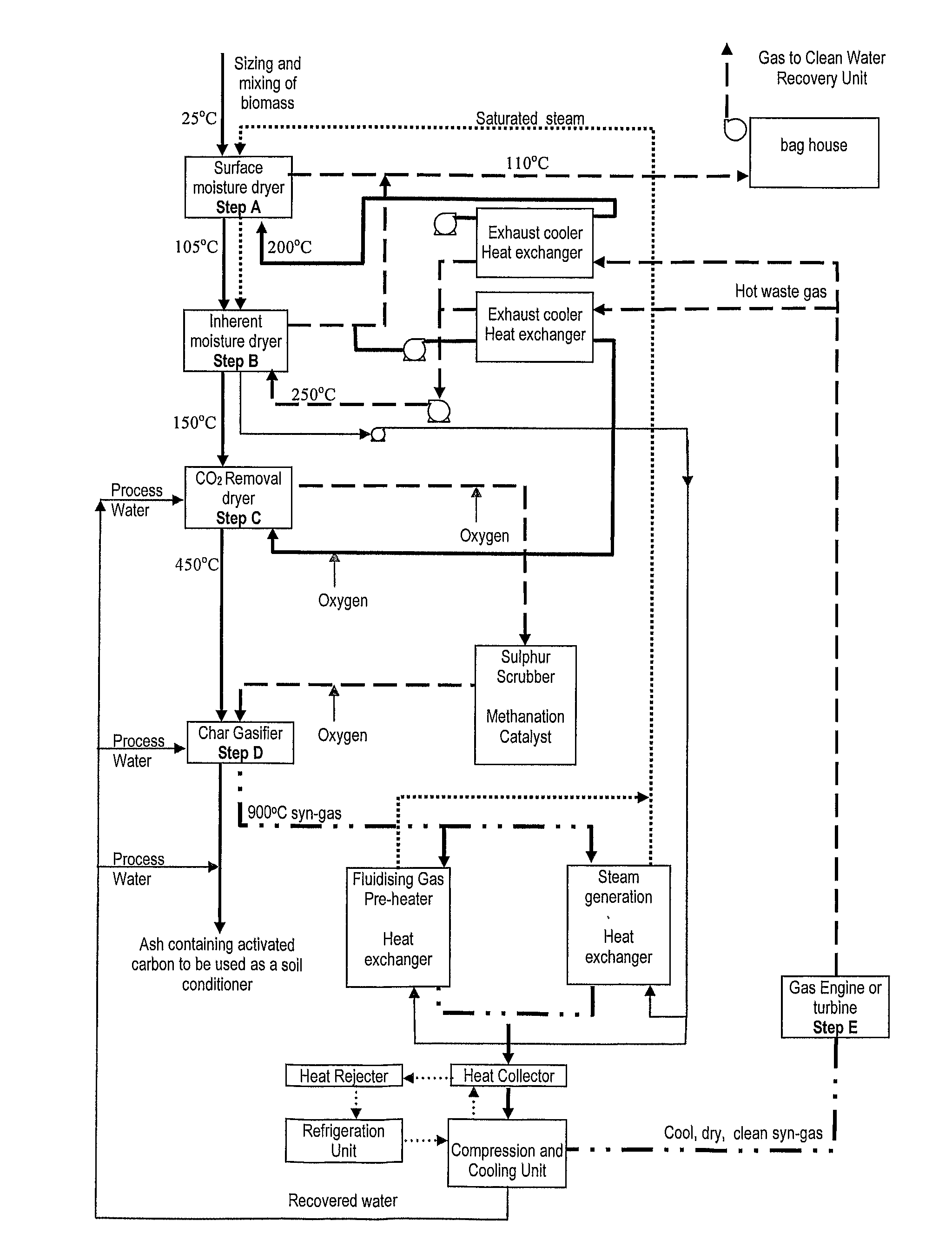
[0086]Example 1 is for a plant to produce a hot bio-char as a feed to a conventional coal based power station. Referring to FIG. 3, there is shown a process flow diagram in accordance with one embodiment of the present invention. As can be seen, the carbonaceous material proceeds through three process steps which ultimately results in the production of low grade syn-gas.

[0087]In the first process step a) the carbonaceous substance enters a surface moisture dryer where the carbonaceous substance is contacted with a hot gas at a temperature of between 115° C. and 400° C. According to this embodiment, the hot gas is a waste gas from the power station. In addition to the direct contact with the hot gas, the surface moisture dryer also indirectly contacts the carbonaceous substance with steam flowing through steam tubes within the dryer. The action of the steam indirectly contacting the carbonaceous substance slowly heats the substance to between 100° C. and 140° C. resulting in the stea...

example 2

[0100]In the following example, fresh leaves and branches have been mechanically pick up from the ground. The average collection rate is 1.25 tonne per hour over the entire year. This biomass material will be brought to the small central plant where the timber is chipped. The power plant is within 25 km of the farm based sustainable timber production. The fuel composition is:

Total Moisture50.00%w.b.Ash10.80%d.b.Carbon46.10%d.b.Hydrogen5.90%d.b.Nitrogen0.60%d.b.Sulfur0.20%d.b.Oxygen36.40%d.b.Specific Energy18.10MJ / kg d.b (gross)

[0101]This amount of biomass, at its stated composition and if it was used in an open cycle power plant would typically produce about 0.46 MW, (gross). This represents an overall conversion efficiency of 15%. This is below economic size for an open cycle power plant.

[0102]However, if this same biomass was used as a feed source for a plant as outlined in the process diagram FIG. 5, this resource could be used quite effectively. In FIG. 5 the wood waste proceeds...


PUM


Abstract

A process for producing syngas from a carbonaceous substance and / or treating a carbonaceous substance, the process including the following steps: a) reducing the surface moisture of the carbonaceous substance; b) reducing the inherent moisture of the carbonaceous substance; and, c) gasifying the carbonaceous substance to produce syngas, wherein at step a) the carbonaceous substance is directly contacted with a hot gas at a temperature of between 50° C. to 250° C., and / or the carbonaceous substance is indirectly contacted with saturated steam at a temperature of between 105° C. and 250° C.

Description

[0001]The present invention relates to a process for drying and subsequently gasifying a carbonaceous substance and in particular a process using carbonaceous substances that have high moisture content.BACKGROUND OF THE INVENTION[0002]In recent times, reducing CO2 emissions has become increasingly important on a global scale, particularly in relation to the production of the world's electricity supply which at present relies heavily on coal fired power stations. Biomass is a renewable energy source that can provide a genuine alternative to coal in that it can be used for base load electricity generation. However, biomass has failed to make a wide spread difference to the local or global energy market for two reasons:[0003]1. Biomass typically has a very high moisture content of 30 to 80%. This usually results in a larger and more expensive boiler plant and lower conversion efficiency of thermal to electrical energy.[0004]2. Biomass is distributed across large areas of land, making c...

Claims


Application Information

Patent Timeline
IPC IPC(8): C10J3/00
CPCC10B53/02C10B57/10C10J3/00C10J3/482C10J3/62C10J3/66C10J2300/0903C10J2300/0909C10J2300/0916C10J2300/093C10J2300/0946C10J2300/0956C10J2300/0973C10J2300/1606C10J2300/165C10J2300/1659C10J2300/1665C10J2300/1807C10K1/004C10L9/08F26B3/084F26B23/001F26B25/005Y02E20/18Y02E50/18Y02E50/32Y02E50/14Y02E20/16Y02P70/405Y02P20/145Y02P20/129Y02E50/10Y02E50/30Y02P70/10
Inventor CORK, DAVID
Owner CORK DAVID
Learn More