Bubble-Less Gas Delivery Into Liquid Systems

a gas delivery and liquid technology, applied in water/sludge/sewage treatment, water treatment parameter control, mixers, etc., can solve the problems of increasing the input treatment cost associated with the addition of organic carbon donor substrates, nitrate contamination of water systems, and numerous significant problems

Inactive Publication Date: 2010-08-12
REZANIA BABAK +2
View PDF5 Cites 20 Cited by
  • Summary
  • Abstract
  • Description
  • Claims
  • Application Information

AI Technical Summary

Benefits of technology

[0020]According to another preferred aspect of the present invention, there is provided a method for controllably saturating liquids with selected gases for delivery to bioreactors. The method provides a closed-system gas-saturation unit consisting of a saturation tank, a liquid inflow line, a liquid pump connected into the liquid inflow line for pumping and precisely regulating the flow of liquids therethrough into the saturation tank, a gas supply line, a gas supply valve, a liquid outflow line, a pressure regulator valve interconnected into the liquid outflow line for precisely controlling the flow of liquid therethrough out of the saturation tank, a microprocessor, a pressure sensor communicable with the microprocessor, and a dissolved gas sensor communicable with the microprocessor. The saturation tank may optionally be fitted with mixing apparatus for commingling liquids and gases introduced into the saturation tank, drainage valves for removal of liquids, pressure relief valves for releasing gases from the headspace, instrumentation communicable with the microprocessor for monitoring and displaying selected physical and chemical parameters within the saturation tank, and controlling devices are interconnected with, communicable with and controllable by the microprocessor for electronically affecting operation of the inflow liquid pump, gas supply valve, and the outflow pressure regulator valve. A selected liquid is pumped into the saturation tank while the outflow pressure regulator valve is in an open position, until a selected volume is reached under ambient conditions. The outflow pressure regulator valve is then closed and a selected gas is introduced into the saturation tank under pressure and commingled with and integrated into the liquid. After the selected degree of saturation is reached, the saturated liquid may be delivered from the saturation unit by controllably opening the outflow pressure regulator valve. If so desired, a constant supply of saturated liquid may be delivered over extended periods from the saturation unit by co-adjusting the outflow regulator valve in communication with the controls for the gas supply and inflow liquid pump whereby constant feeds of inflow liquid and gas are supplied in communication with the outflow delivery of saturated liquid. As illustration of how this method may be practised, under ambient atmospheric pressure and a temperature of 20° C., the maximum solubility of hydrogen gas in water is about 1.62 mg / L. Addition of hydrogen gas into water contained in an open-system will result in hydrogen gas bubbles formed within the matrix of water molecules wherein the gas bubbles will turbulently rise to the water surface and dissipate into the atmosphere. However, when hydrogen gas is introduced into the closed-system saturation unit with the pressure regulator valve closed and filled with water to a selected level, the hydrogen molecules will be increasingly integrated into the water molecules as increasing amounts of hydrogen gas are introduced under pressure into saturation tank. It is possible with this method to attain concentrations of dissolved hydrogen on the order of 16.2 mg / L and greater if so desired. It is possible to provide a constant supply by controllably adjusting the flow rate of gas-saturated liquid through the liquid outflow line in co-reference to the rate of gas supply and the flow rate of liquid through the liquid inflow line.
[0021]According to a further preferred aspect of the present invention, there is provided a method for supplying a flow of gas-saturated liquid to a bioreactor at a rate controllably adjusted to the rate of biological consumption of the gas within the bioreactor, thereby avoiding loss of gas from the saturated liquid in form of bubbles dissipating into the bioreactor head space. The saturation tank is equipped with sensing devices and instrumentation for repeated or optionally, continual measurements and monitoring of the concentration of one or more solubilized gases in the liquid added to and contained within the saturation tank. The gas monitoring equipment is electronically communicable with a microprocessor configured to communicate with and control the liquid feed pump, gas supply valve and / or the pressure regulator valve. The bioreactor is equipped with sensing devices and instrumentation in communication with the microprocessor for repeated or optionally, continual measurements and monitoring of the concentration of one or more solubilized gases in a liquid system contained within the bioreactor. The bioreactor gas monitoring equipment is also electronically communicable with a microprocessor configured to communicate with and control the liquid feed pump whereby the rate of flow of gas-saturated liquid through the outflow pressure regulator valve is modulated in response to electronic signals received from the bioreactor and the gas-saturation tank.

Problems solved by technology

Nitrate contamination of water systems presents numerous significant problems and issues for governments and industries around the world because of the impacts on: (a) the availability and supply of safe drinking water, (b) ameliorating and reducing the effects of pollution on fragile ecosystems, and (c) the costs and liabilities associated with management of waste streams generated by industrial processes and urbanization.
The largest source of nitrate contamination comes from intensive farming practices, primarily heavy fertilization of crops and significant animal waste production in confined spaces.
Significant contamination also comes into water systems through discharges from industrial waste streams and municipal sewage plants, and also from nitrogen oxide emissions into the atmosphere from the burning of hydrocarbon fuels which are consequently incorporated into precipitation.
The disadvantages include the increased input treatment costs associated with the added organic carbon donor substrates, elevated sludge production and associated removal costs, organic carbon donor residuals remaining in treated water thereby contributing to unpalatable odours and tastes which require further post-denitrification treatments for clarification and deodorization of denitrified water.
However, hydrogen gas is difficult to handle-safely and economically in large systems due to its low solubility which results not only in low mass transfer rates into microbial processes, but also rapidly dissipates into headspaces above the liquid systems thereby causing potential explosion hazards.
Disadvantages associated with elemental sulfur-based autotrophic denitrification using suspended microbial cultures, include poor mixing and distribution of sulfur throughout liquid substrates in closed-system bioreactors due to elemental sulfur's low specific gravity, poor microbial culture development and denitrification performance when influents contain relatively low nitrate concentrations, a tendency to build-up concentrations of nitrites and sulfates when influents contain higher nitrate concentrations to levels whereby feedback inhibition of the denitrification process occurs thus limiting its efficiency.
Disadvantages associated with sulfur-reducing autotrophic denitrification systems wherein the inorganic carbon is supplied in solid forms include the inability to maintain constant high rates of denitrification over extended periods of time as the biofilms grow thicker and more dense around the solid inorganic carbon sources.
Therefore, costly scouring methods and equipment must be employed to dislodge and manage biofilm development and performance.
A further disadvantage with all sulfur-based autotrophic denitrification systems is the production of malodorous hydrogen disulfide gas that must be collected and reconverted into reusable forms of sulphate.
However, although these membranes show very high hydrogen transfer rates during start-up stages, there are numerous impediments that currently limit the applications for membrane-based hydrogen delivery in long-term denitrification installations.
The main limitations include:1. The membranes are very fragile and any physical damage to the membrane causes bubble formation and ineffective hydrogen delivery.2. In cases where membrane diffusers are in direct contact with biological medium, their mass transfer efficiency decreases.3. Biofilms grown on membrane surfaces are usually thick thereby reducing the efficiency of hydrogen uptake as the biofilm expands.
Furthermore, scouring or sheering biofilms from the membrane surfaces is difficult due to precipitation of inorganic compounds inside the biofilm mass.4. The hydrophobicity of the membranes change over time due to condensation of water vapour inside the biofilm.
The changes in hydrophobicity of the membranes make them vulnerable to irreversible fouling.

Method used


Image

  • Bubble-Less Gas Delivery Into Liquid Systems
  • Bubble-Less Gas Delivery Into Liquid Systems
  • Bubble-Less Gas Delivery Into Liquid Systems

Examples


example 1

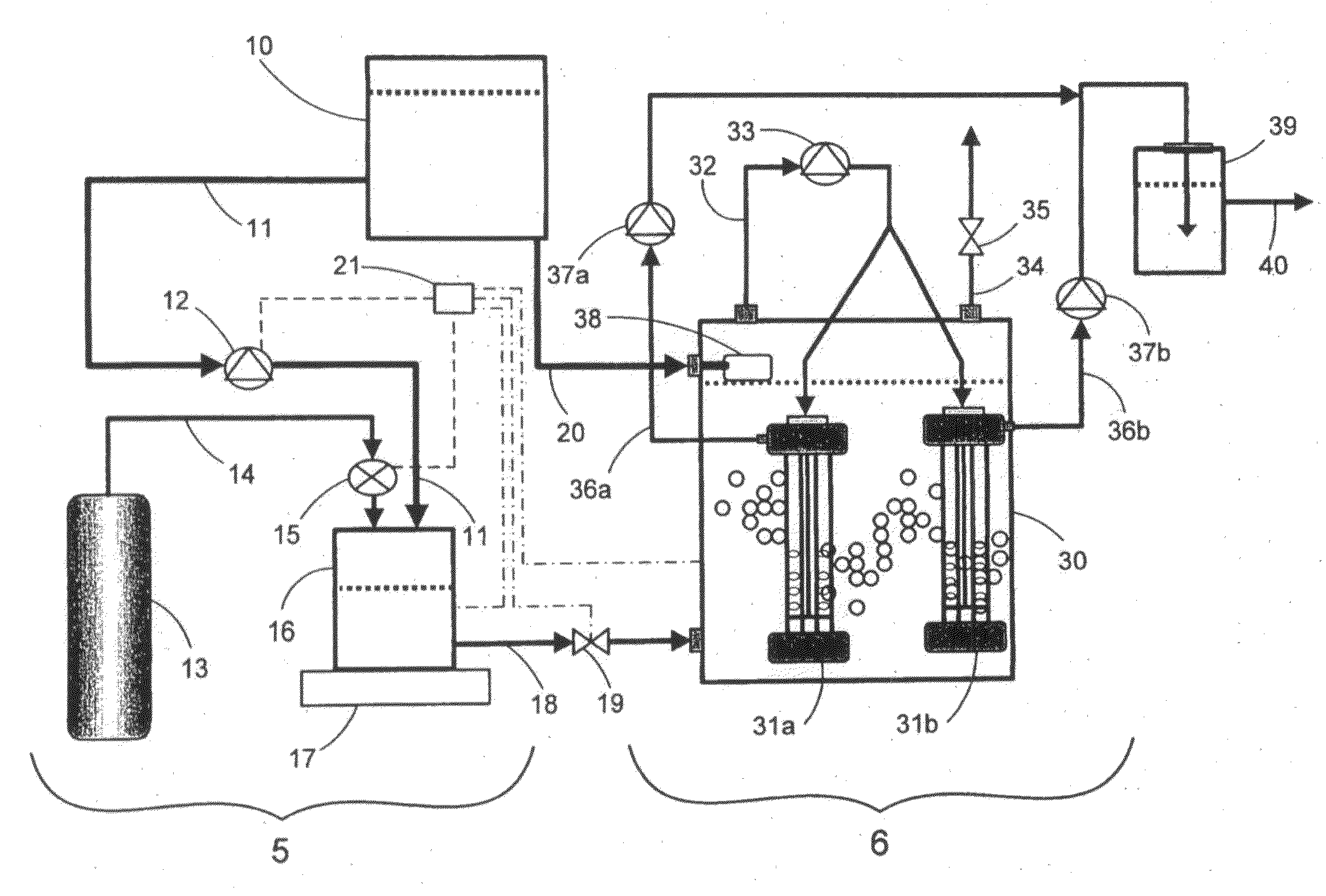
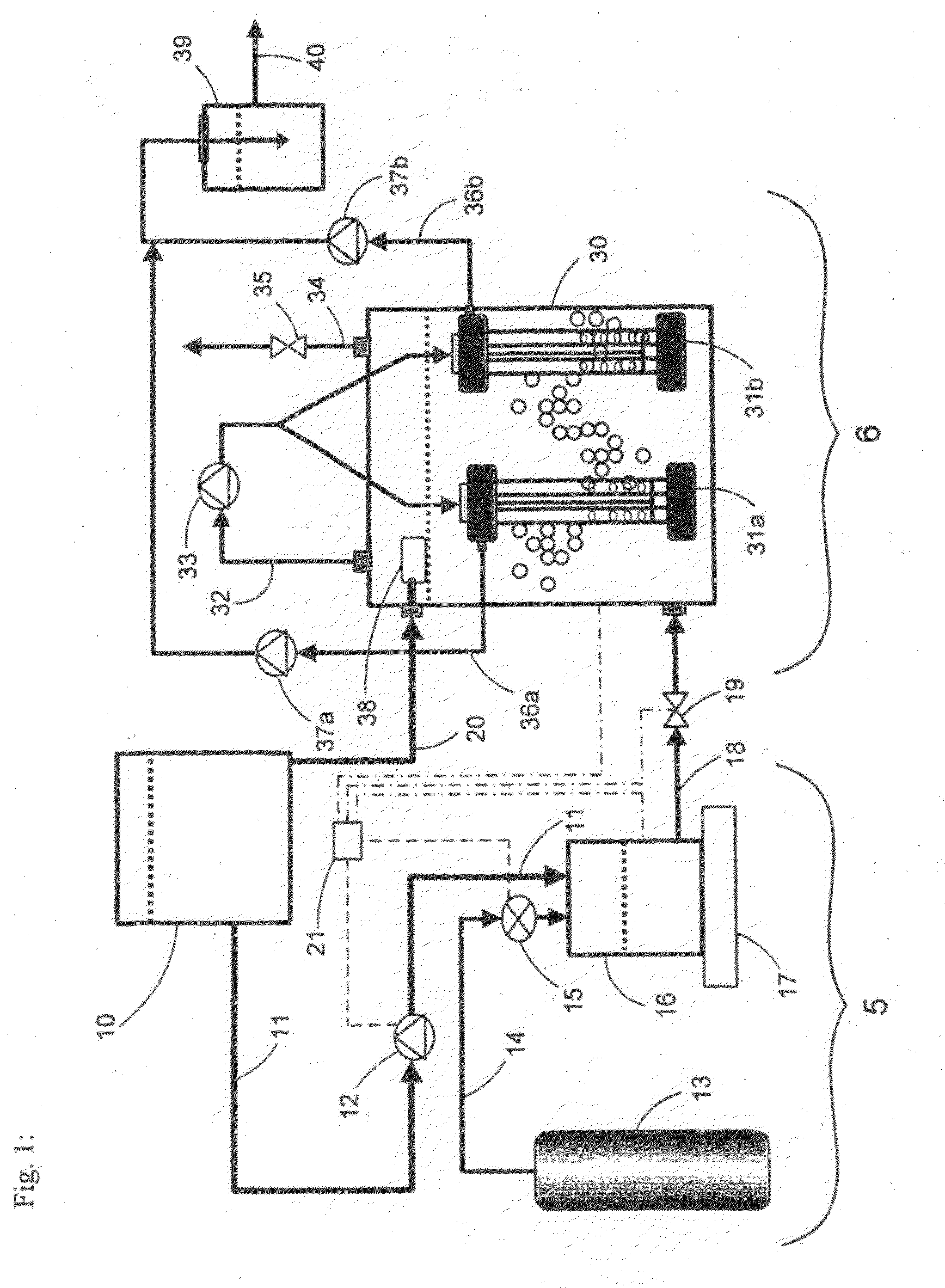
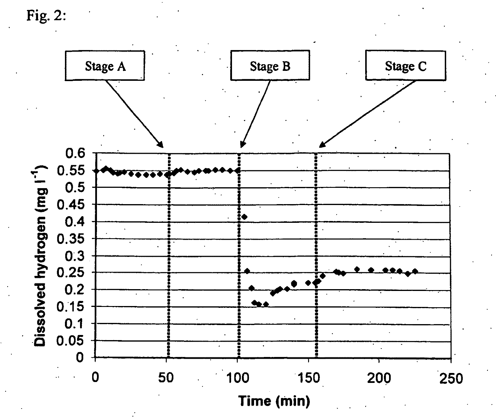
[0041]An experiment using the preferred embodiment of the present invention illustrated in FIG. 1 was conducted to assess the mass transfer of hydrogen gas from supersaturated water released from the saturation mixing tank 16 into unsaturated water contained within the bioreactor unit 6. Pure water contained in storage tank 10 was pumped into the bioreactor vessel 30 after which, the headspace in the bioreactor vessel 30 was filled with nitrogen gas. Hydrogen gas was released from the gas cylinder 13 into the gas saturation mixing tank 16 until a pressure of 120 psi was reached. Then, water was pumped from the storage tank 10 into the gas saturation mixing tank 16 at a flow rate of 37 mL / min and was continuously mixed by agitator 17. The working pressure of outflow regulator valve 19 interconnected with liquid outflow line 18 was adjusted to 125 psi thereby maintaining pressure within the gas saturation mixing chamber at 125 psi. Hydrogen-saturated water was then controllably introd...

example 2

[0043]An experiment using the preferred embodiment of the present invention illustrated in FIG. 1 was used to assess denitrification of a high-nitrate synthetic wastewater. The synthetic wastewater was prepared by dissolving 25 mg L−1 NO3—N, 1000 mg L−1 NaHCO3, 25 mg L−1 KH2PO4, 5 mg L−1 CaCl2, 25 mg MgSO4.7H2O and 1 mg L−1 FeSO4 in pure water. The storage tank 10 and the bioreactor vessel 30 were filled with the synthetic wastewater while the gas saturation mixing tank 16 was filled with hydrogen gas from gas cylinder 13 until the pressure inside tank 16 was 120 psi. The synthetic wastewater transferred into the bioreactor vessel 30 was then inoculated with wastewater-activated sludge containing hydrogenotrophic denitrifying bacteria. The wastewater-activated sludge was obtained from a municipal water treatment facility located in Winnipeg, Manitoba, Canada. The working pressure of the outflow pressure regulator valve 19 interconnected to the liquid outflow line 18 was adjusted to ...

example 3

[0050]The preferred embodiment of the present invention illustrated in FIG. 1 was used to assess denitrification of a final effluent containing high nitrate levels produced by a municipal water treatment facility located in Winnipeg, Manitoba, Canada. The storage tank 10 and the bioreactor vessel 30 were filled with the municipal final effluent, while the gas-saturation mixing tank 16 was filled with hydrogen gas from gas cylinder 13 until the pressure inside the gas saturation tank 16 was 120 psi. The municipal final effluent transferred into the bioreactor vessel 30 was then inoculated with wastewater-activated sludge containing hydrogenotrophic denitrifying bacteria. The wastewater-activated sludge was obtained from the same municipal water treatment facility. The working pressure of the outflow pressure regulator valve 19 interconnected to the liquid outflow line 18 was adjusted to 125 psi, thereby maintaining pressure within the gas saturation mixing chamber at 125 psi. Municip...


PUM

PropertyMeasurementUnit
solubilityaaaaaaaaaa
concentrationsaaaaaaaaaa
total volumeaaaaaaaaaa

Abstract

A system for saturating a liquid with a gas followed by bubble-less delivery and mixing of the gas-saturated liquid into a gas-unsaturated liquid wherein a biological process is occurring. The system comprises a gas-saturation unit which controllably communicates with a bioreactor unit containing a gas-unsaturated liquid wherein a biological process is occurring. The gas saturation unit comprises a sealable pressure-resistant vessel for receiving therein an unsaturated liquid and wherein the liquid is saturated with a gas under pressure. The rate of introduction of gas-saturated liquid into the bioreactor unit is controllable to make it equivalent to the rate of gas consumption by the biological process occurring in gas-unsaturated liquid contained within the bioreactor unit. The invention is particularly useful for bubble-less gas delivery to open and closed bioreactor configurations for wastewater treatment processes.

Description

TECHNICAL FIELD[0001]The present invention relates to the field of bubble-less gas delivery into liquids, and more particularly, to saturation of liquids with gases for affecting processes in liquid systems.BACKGROUND ART[0002]While the invention is useful for many applications, it is directed in particular to the purification of contaminated water systems.[0003]Nitrate contamination of water systems presents numerous significant problems and issues for governments and industries around the world because of the impacts on: (a) the availability and supply of safe drinking water, (b) ameliorating and reducing the effects of pollution on fragile ecosystems, and (c) the costs and liabilities associated with management of waste streams generated by industrial processes and urbanization. The largest source of nitrate contamination comes from intensive farming practices, primarily heavy fertilization of crops and significant animal waste production in confined spaces. Significant contamina...

Claims


Application Information

Patent Timeline
Patent Type & Authority Applications(United States)
IPC IPC(8): C02F3/00B01F3/04
CPCB01F3/04099B01F3/04269B01F13/1027B01F15/00162B01F15/00207C02F2209/40C02F3/006C02F3/102C02F3/28C02F2209/03B01F15/0022Y02W10/10B01F23/23B01F23/23124B01F33/821B01F35/2113B01F35/213B01F35/2132
Inventor REZANIA, BABAKOLESZKIEWICZ, JANCICEK, NAZIM
Owner REZANIA BABAK
Why Eureka
Try Eureka