Synthesis of advanced scintillators via vapor deposition techniques

a scintillator and vapor deposition technology, applied in the field of xray detectors, can solve the problems of limited commercial feasibility and limited small detector area, and achieve the effects of high atomic number, superior radiological imaging, and high efficiency in capturing high-energy photons

Inactive Publication Date: 2010-08-12
TRUSTEES OF BOSTON UNIV
View PDF2 Cites 13 Cited by
  • Summary
  • Abstract
  • Description
  • Claims
  • Application Information

AI Technical Summary

Benefits of technology

[0004]The invention provides scintillator coating materials and films that provide superior radiological imaging. The materials are based on lutetium (e.g., Lu2O3, Lu2SiO5, etc.), which has a high atomic number and is therefore highly efficient at capturing high energy photons, such as x-rays. The lutetium is in the form of, for example, lutetium oxide (Lu2O3) doped with europium oxide (Eu2O3). The lutetium oxide and europium oxide form a solid solution having an oriented columnar grain growth pattern. Lutetium serves to trap incident x-rays, whose energy is transferred to europium, causing an electron orbital shift in europium that results in the release of visible light photons. The columnar growth structure eliminates the need for pixelation and provides highly efficient light transmission out of the scintillator material. The emitted visible light is in a wavelength range that can be imaged with high efficiency using solid state silicon devices such as CCDs.

Problems solved by technology

However, they have generally been limited to small area detectors due to manufacturing limitations.
With current fabrication technology, this is not commercially viable, due to the required processing.

Method used


Image

  • Synthesis of advanced scintillators via vapor deposition techniques
  • Synthesis of advanced scintillators via vapor deposition techniques
  • Synthesis of advanced scintillators via vapor deposition techniques

Examples


example 1

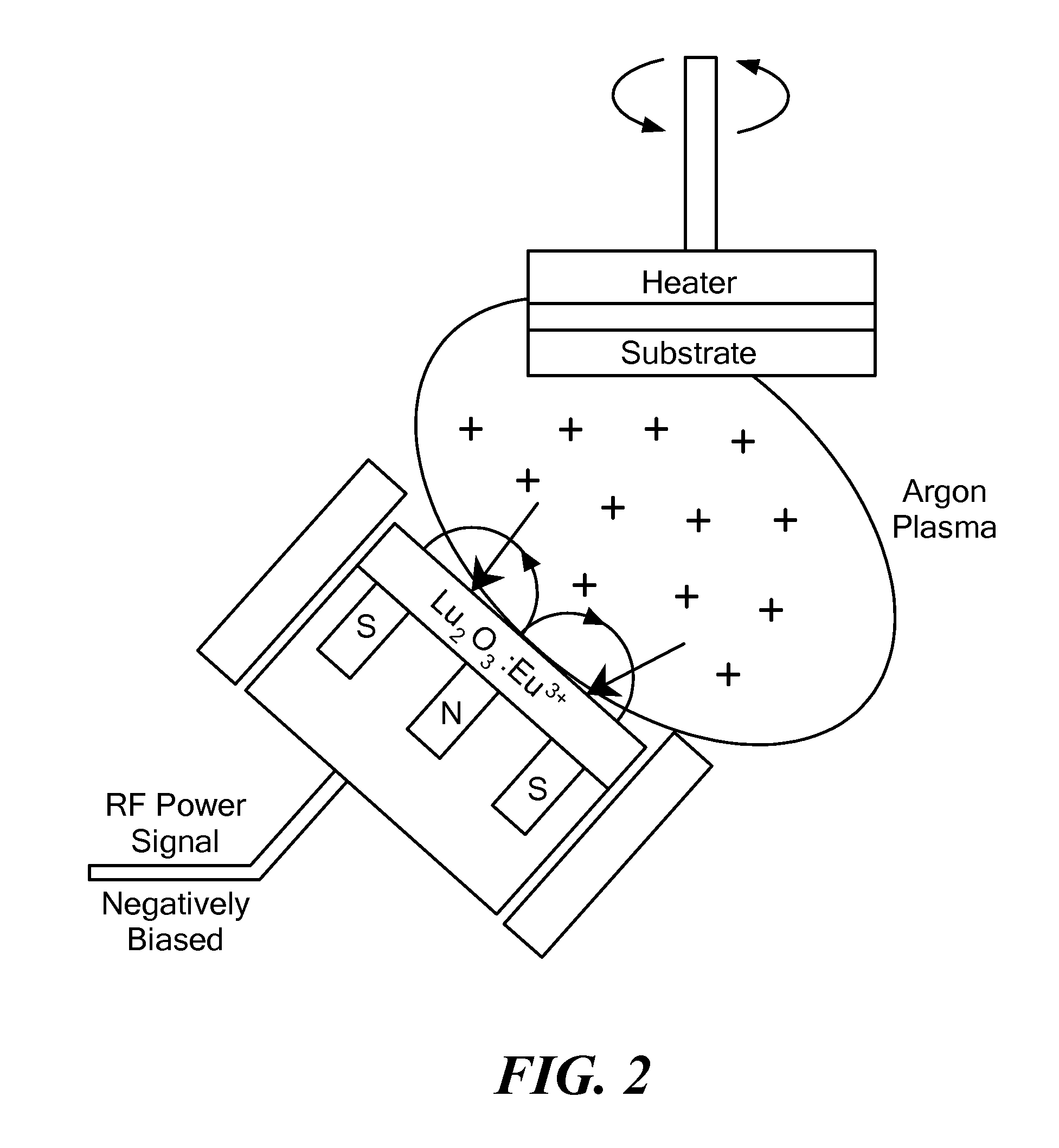
Physical Vapor Deposition of Lu2O3:Eu Films

[0042]Films of Lu2O3:Eu3+ were successfully deposited using physical vapor deposition (PVD) carried out in a radio frequency (RF) magnetron sputtering device (see FIG. 2). The setup used a 2 inch diameter target angled at 45 degrees with respect to the substrate. The target was made by hot pressing Lu2O3 powder doped with 5 mol % Eu2O3 at 1700° C. using a graphite uniaxial hot press. A thin 2 inch diameter graphite disc was used as the substrate and it was rotated at approximately 20 rpm to increase uniformity. The RF power source was an Advanced Energy RFX600 capable of producing 600 Watts. Coatings were deposited at 50, 75 and 100 watts and examined. It was determined that 100 watts was the maximum useable power level, above which charging and target damage occurred. The coatings were examined using a Bruker D8 Focus X-ray diffraction (XRD) unit using Cu-Kα radiation to determine orientation, and a Zeiss field emission scanning electron m...

example 2

PVD Films Deposited on Heated Substrates

[0045]Deposition by PVD at a substrate temperature of 400° C. resulted in a coating that exhibits a significantly higher degree of orientation than that obtained at room temperature. FIG. 5A shows a plot of the XRD data for films deposited at increasing substrate temperature. The peaks remain slightly shifted toward higher unit cell dimensions, indicating some residual stress and suggesting the need for even greater thermal energy, perhaps by heating to 700-900° C. The micrograph of these fracture cross-sections (FIG. 5B) reveals a columnar structure, and the corresponding surface micrograph (FIG. 5C) contains randomly oriented pyramidal shapes similar to the 75 W coating in FIG. 3, suggesting that heated substrates accommodate higher material fluxes than they would otherwise tolerate at room temperature.

example 3

Effect of Heat Treatment on Lu2O3:Eu Films Deposited by PVD

[0046]To study the effects of annealing by heat treatment, coatings were post-treated in a tungsten furnace at 900° C. in an argon atmosphere for 2 hours. The samples from Example 1 were heat treated to increase crystallinity and observe changes in morphology. As seen in FIG. 17, the (100) peak reverted back to the theoretical position after heat treatment, indicating stress relief. However, associated with the restored unit cell is a subsequent volume change resulting in reduced thickness and cracking (FIG. 17). In the 100 W case, the volume distortion led to loss of adhesion, making further analysis on the heat treated sample almost impossible. One can observe in FIG. 17 that the morphology of the coating remained identical to the as-deposited coating, indicating stability of the coating. A small increase in the intensity of the (100) peak was observed, indicating slight grain growth or increase in crystallinity. In FIG. 1...


PUM

PropertyMeasurementUnit
pressureaaaaaaaaaa
temperatureaaaaaaaaaa

Abstract

Transparent optical ceramic coating materials have been fabricated from europium-doped lutetium oxide (Lu2O3:Eu) using physical vapor deposition and chemical vapor deposition techniques. The non-pixilated film coatings have columnar microcrystalline structure and excellent properties for use as radiological scintillators, namely very high density, high effective atomic number, and light output and emission wavelength suitable for use with silicon-based detectors having a very high quantum efficiency. The materials can be used in a multitude of high speed and high resolution imaging applications, including x-ray imaging in medicine.

Description

STATEMENT REGARDING FEDERALLY SPONSORED RESEARCH OR DEVELOPMENT[0001]The research leading to this invention was carried out with U.S. Government support provided under Grant No. 5R21EB005037 from the National Institutes of Health. The U.S. Government has certain rights in the invention.BACKGROUND[0002]Rare earth oxides are used in the x-ray detector industry due to their stability, high density, and high atomic number. However, they have generally been limited to small area detectors due to manufacturing limitations. The present industry standard scintillator for x-ray detection is cesium iodide doped with tantalum (CsI:Tl). In terms of optical and scintillation properties, CsI:Tl has good transparency, a density of 4.51 g / cc, and emits ˜60,000 photons per MeV of incident x-rays [1]. Lutetium Oxide doped with Europium Oxide (Lu2O3:Eu) has been studied as an alternative to CsI:Tl, because its high density and high atomic number make it an ideal scintillator. Lu2O3:Eu has a highly tra...

Claims


Application Information

Patent Timeline
Patent Type & Authority Applications(United States)
IPC IPC(8): C09K11/78C23C16/06C23C14/35G01T1/20
CPCC09K11/7787C23C14/08C23C14/35A61B6/42G21K4/00G21K2004/06C23C16/40
Inventor SARIN, VINOD K.TOPPING, STEPHEN GIBSON
Owner TRUSTEES OF BOSTON UNIV
Why Eureka
Try Eureka