Substrate for solar cell and solar cell

a solar cell and substrate technology, applied in the direction of coatings, semiconductor devices, surface reaction electrolytic coatings, etc., can solve the problems of glass substrates that cannot be easily damaged, and lack of flexibility limits the scope of application, so as to achieve good insulating properties and good adhesion , good voltage resistance characteristics

Inactive Publication Date: 2010-09-02
FUJIFILM CORP
View PDF5 Cites 65 Cited by
  • Summary
  • Abstract
  • Description
  • Claims
  • Application Information

AI Technical Summary

Benefits of technology

[0010]The present invention has been made in view of the above circumstances. The present invention is to provide a substrate for a solar cell containing a metal substrate and an insulating layer provided thereon, which is flex...

Problems solved by technology

However, a glass substrate is fragile and must be treated with considerable care and its lack of flexibility limits the scope of the application.
However, a glass substrate would be even more fragile if it is thinned for reduction in weight.
If a metal is used as such a substrate material, its insulation from a solar cell material arranged thereon is difficult, while a resin substrate cannot withstand a high temperature exceeding 400° C. that is necessary to form a solar cell.
Use of a metal substrate also causes a problem in which the thermal expansion coefficient of the metal substrate differs from that of the semiconductor layer of the photoelectric conversion layer, so that the semiconductor layer is susceptible to peeling.
However, this method also has a problem that a sufficient breakdown voltage is not obtained.
However, there is a problem in which when such an insulating layer is formed only on one side, the shape may be curved due to the difference in therma...

Method used


Image

  • Substrate for solar cell and solar cell
  • Substrate for solar cell and solar cell
  • Substrate for solar cell and solar cell

Examples


example 1

[0221]The Al alloy substrates shown in Table 6 below were used. Anodic oxide films of varying thicknesses were formed on both sides of the aluminum substrates in an aqueous 0.5 M oxalic acid solution at 16° C. under the anodizing conditions of a voltage of 40 V using a DC power source. The anodic oxide films were then washed with water and dried.

[0222]The substrates were then subjected to pore sealing treatment by dipping them in a solution containing sodium fluoride and phosphoric acid, which had a pH of 4.0 and was heated to 75° C., so that anodized aluminum films of varying sealing ratios were formed.

[0223]The surface areas of the anodic oxide films before and after the pore sealing treatment were measured using a simple BET surface area analyzer (QUANTASORB (trade name) manufactured by Yuasa Ionics Inc.), and the sealing ratios were calculated according to the formula below.

Sealing ratio (%)=[(surface area of anodic oxide film before pore-sealing treatment−surface area of anodic...

example 2

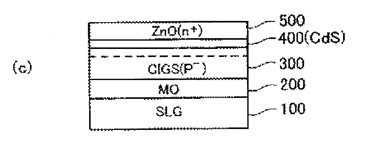
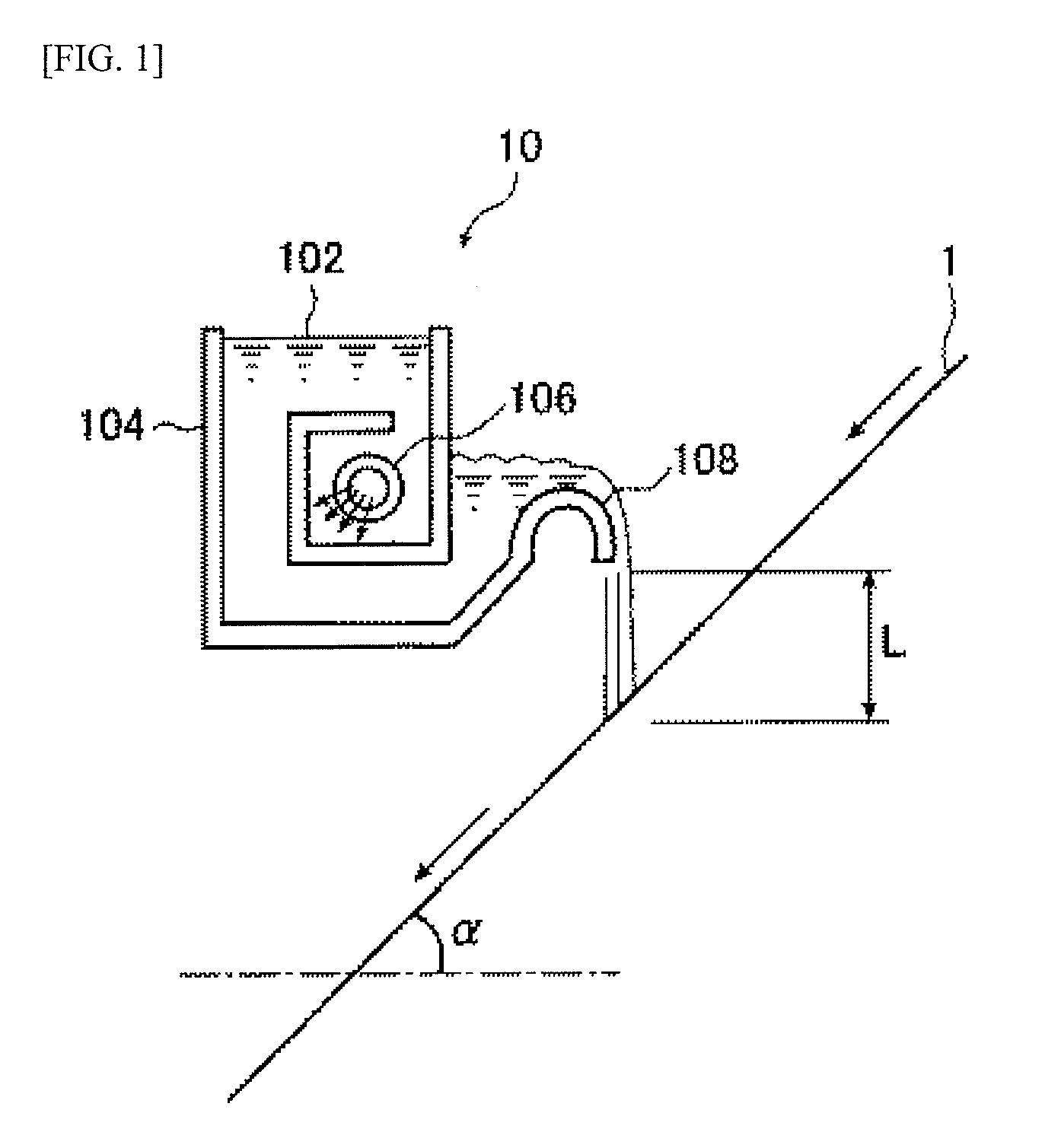
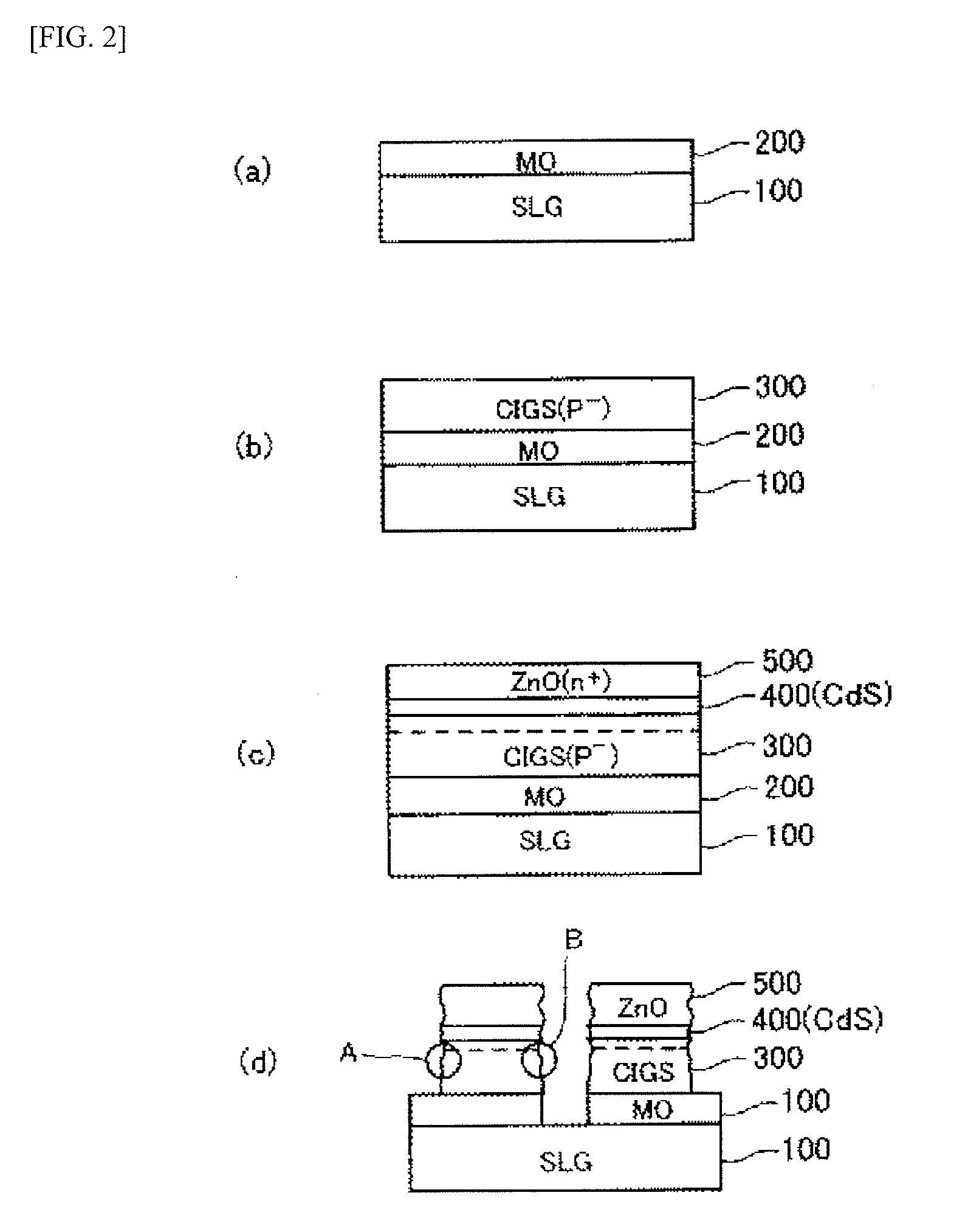
[0235]A CIGS solar cell was formed on each of a glass substrate, a stainless substrate, and an anodized aluminum substrate by a film forming method, and the weights of the resulting solar battery cells per 1 m2 were compared with one another. As the anodized aluminum substrate, the anodized aluminum substrates No. 1 and 7 produced in Example 1 were used. In this example, disc-shaped targets of high-purity copper, indium (99.9999% in purity), high-purity Ga (99.999% in purity), and high-purity Se (99.999% in purity) were used.

[0236]The thicknesses of the glass substrate, the stainless substrate and the anodized aluminum substrate were 2 mm, 0.10 mm and 0.10 mm, respectively. A 0.8 μm thick molybdenum film was deposited on each of these substrates by sputtering. A chromel-alumel thermocouple was used as a substrate temperature monitor.

[0237]First, the main vacuum chamber was evacuated to 10−6 Torr, and then high-purity argon gas (99.999%) was introduced into the sputtering chamber, an...

example 3

[0242]In this example, a chalcopyrite structure CuInGaSe2 thin film was formed as a CIGS thin film. In this example, an anodized aluminum substrate, a stainless substrate, and a soda-lime glass substrate were each used, on which films were formed under the same conditions as those in Example 2 to form solar cells. As the anodized aluminum substrate, the anodized aluminum substrate No. 6, 9 and 12 produced in Example 1 were used.

[0243]The characteristics of each resulting solar cell were measured, while it was irradiated with simulated sunlight at an AM of 1.5 and 100 mW / cm2. As a result, the solar cells produced with the anodized aluminum substrate Nos. 6, 9 and 12, respectively, had conversion efficiencies of 14%, 7%, and 5%, respectively. The solar cells produced with the soda-lime glass substrate and the stainless substrate, respectively, had photoelectric conversion efficiencies of 13% and 5%, respectively.

[0244]It is considered that the solar cell produced with the anodized alu...


PUM

PropertyMeasurementUnit
Fractionaaaaaaaaaa
Thicknessaaaaaaaaaa
Thicknessaaaaaaaaaa

Abstract

A substrate for a solar cell having a metal substrate, a first insulating oxide film formed on the metal substrate by anodic oxidation, and a second insulating film, wherein the first insulating oxide film has pores and the pores are sealed with the second insulating film at a sealing ratio of 5 to 80%.

Description

TECHNICAL FIELD[0001]The present invention relates to a substrate for a solar cell that has flexibility and excellent voltage resistance characteristics and provides excellent adhesion properties to an upper layer to form a thin-film solar cell; and also relates to a solar cell using the same.BACKGROUND ART[0002]Glass substrates are mainly used as thin-film solar cell substrates. However, a glass substrate is fragile and must be treated with considerable care and its lack of flexibility limits the scope of the application. Recently, solar cells have attracted much attention as power supply sources to buildings including homes. It is inevitable to upsize solar cells in order to ensure sufficient electric power to supply, and there has been a demand for a more lightweight substrate that should contribute to production of solar cells with larger areas.[0003]However, a glass substrate would be even more fragile if it is thinned for reduction in weight. Therefore, there has been a demand...

Claims


Application Information

Patent Timeline
IPC IPC(8): H01L31/00
CPCC25D11/02C25D11/04C25D11/12C25D11/18Y02E10/541H01L31/0392H01L31/03928H01L31/0749H01L31/0322H01L31/03925
Inventor AONO, NARUHIKOHOSOYA, YOUICHIYAGO, HARUOSATO, TADANOBU
Owner FUJIFILM CORP
Why Eureka
Try Eureka