
Method for determining asphaltene stability of a hydrocarbon-containing material

a hydrocarbon-containing material and asphaltene technology, applied in the direction of tar working up by chemical refining, thermal non-catalytic cracking, instruments, etc., can solve the problems of asphaltene precipitation, limited efficiency of converting such hydrocarbon materials, and increase the tendency of asphaltenes to agglomerate into larger particles, etc., to achieve effective determination of stability for asphaltene concentrations lower, cost efficient and repeatable

Inactive Publication Date: 2011-03-17
CHEVROU USA INC
View PDF15 Cites 31 Cited by
  • Summary
  • Abstract
  • Description
  • Claims
  • Application Information

AI Technical Summary

Benefits of technology

[0043]The method of the present invention advantageously determines the asphaltene stability of a hydrocarbon-containing material having solvated asphaltenes therein in a simple, cost efficient and repeatable manner. In this way, the hydrocarbon-containing material can be readily characterized to allow for the design and monitoring of processes such as refining and production operations for the hydrocarbon-containing material such as crude oils.
[0044]In addition, the method of the present invention allows for the use of a small amount of sample and is faster than traditional titration techniques used to evaluate stability and has the potential to be used in or on-line (i.e., automated). The method can also be used at higher temperatures than conventional techniques, substantially closer to process conditions, and can effectively determine stability for asphaltene concentrations lower than, for example, about 1%.

Problems solved by technology

However, when using conventional refinery processes, the efficiency of converting such hydrocarbon material may be limited by transition of the hydrocarbon material of homogeneous mixture to a hydrocarbon material of heterogeneous mixture.
However, changes in pressure, temperature or concentration of the crude oil can alter the stability of the dispersion and increase the tendency of the asphaltenes to agglomerate into larger particles.
One of the problems encountered in crude oil production and refining is asphaltene precipitation.
Generally, unwanted asphaltene precipitation is a concern to the petroleum industry due to, for example, plugging of an oil well or pipeline as well as stopping or decreasing oil production.
Also, in downstream applications, asphaltenes are believed to be the source of coke during thermal upgrading processes thereby reducing and limiting yield of residue conversion.
In catalytic upgrading processes, asphaltenes can contribute to catalyst poisoning by coke and metal deposition thereby limiting the activity of the catalyst.
Asphaltenes can also cause fouling in, for example, heat exchangers and other equipment in a refinery.
Fouling in heat transfer equipment used for streams of petroleum origin can result from a number of mechanisms including chemical reactions, corrosion and the deposit of materials made insoluble by the temperature difference between the fluid and heat exchange wall.
The presence of insoluble contaminants may exacerbate the problem: blends of a low-sulfur, low asphaltene (LSLA) crude oil and a high-sulfur, high asphaltene (HSHA) crude, for example, may be subject to a significant increase in fouling in the presence of iron oxide (rust) particulates.
Subsequent exposure of the precipitated asphaltenes over time to the high temperatures then causes formation of coke as a result of thermal degradation.
Equipment fouling is costly to petroleum refineries and other plants in terms of lost efficiencies, lost throughput, and additional energy consumption, and, with the increased cost of energy, heat exchanger fouling has a greater impact on process profitability.
Higher operating costs also accrue from the cleaning required to remove fouling.
While many types of refinery equipment are affected by fouling, cost estimates have shown that the majority of profit losses occur due to the fouling of whole crude oils, blends and fractions in pre-heat train exchangers.
It has been recognized as a nearly universal problem in design and operation of refining and petrochemical processing systems, and affects the operation of equipment in two ways.
First, the fouling layer has a low thermal conductivity.
This increases the resistance to heat transfer and reduces the effectiveness of the heat exchangers.
Second, as deposition occurs, the cross-sectional area is reduced, which causes an increase in pressure drop across the apparatus and creates inefficient pressure and flow in the heat exchanger.
One of the more common causes of rapid fouling, in particular, is the formation of coke that occurs when crude oil asphaltenes are overexposed to heater tube surface temperatures.
The liquids on the other side of the exchanger are much hotter than the whole crude oils and result in relatively high surface or skin temperatures.
Another common cause of rapid fouling is attributed to the presence of salts and particulates.
The cleaning process, whether chemical or mechanical, in petroleum refineries and petrochemical plants often causes costly shutdowns.
The use and storability of these oil raffinates are impaired by the poor solubility or precipitation of asphaltenes in the oil.

Method used


Image

  • Method for determining asphaltene stability of a hydrocarbon-containing material
  • Method for determining asphaltene stability of a hydrocarbon-containing material
  • Method for determining asphaltene stability of a hydrocarbon-containing material

Examples


example 1

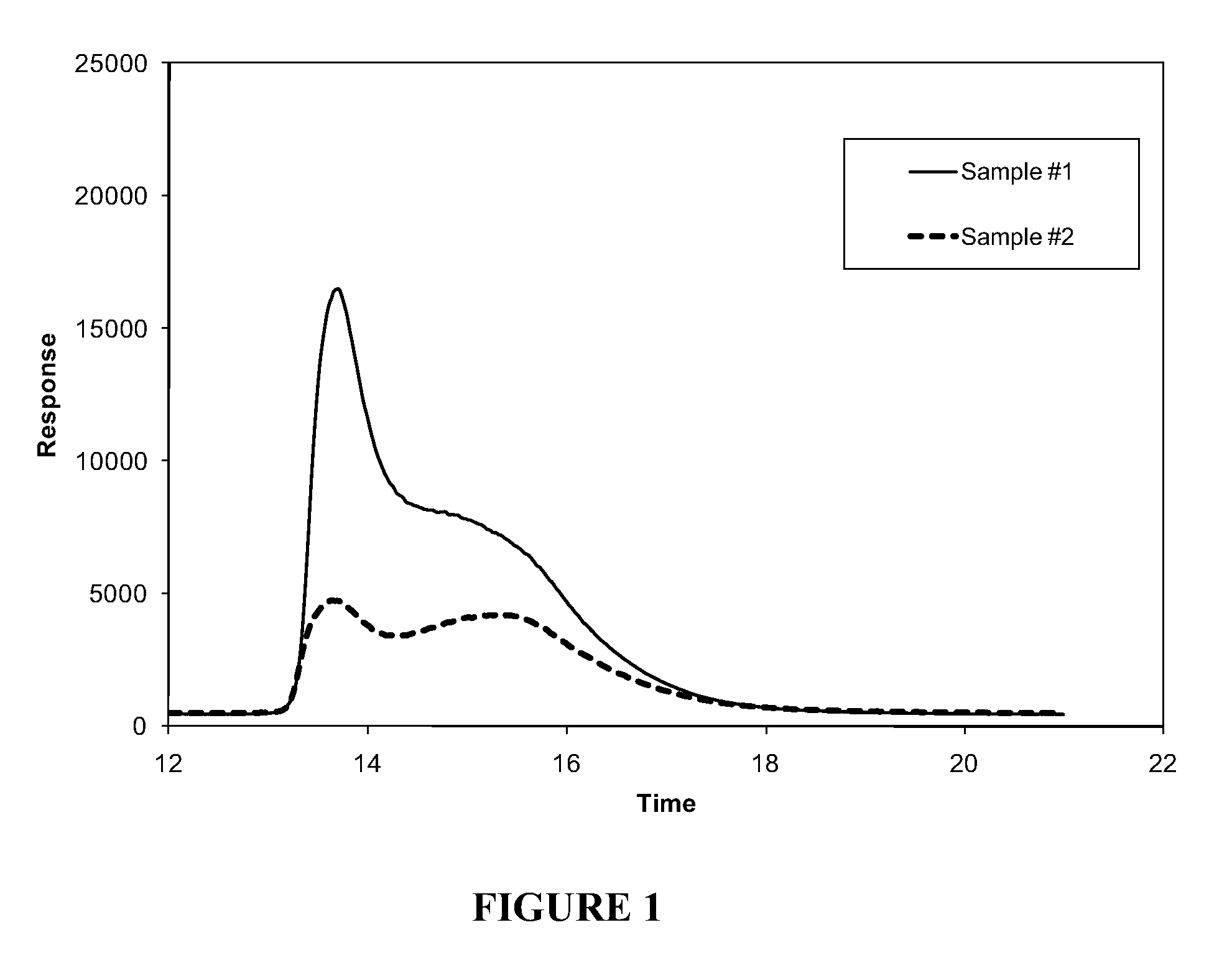
[0099]Typical solubility profile distributions for different materials.

[0100]Solutions of two heavy crude oils from Venezuela (Sample #1) and Mexico (Sample #2), respectively, were prepared by dissolving 0.1000 g of the heavy crude oil in 10 mL of methylene chloride. Both solutions were injected into a separate stainless steel column packed with poly(tetrafluoroethylene) (PTFE) using a heptane mobile phase at a flow rate of 4 mL / min. The maltenes (heptane solubles) eluted from the column as the first peak around 2 minutes after the injection. After 10 minutes, a final mobile phase of 90 / 10 methylene chloride / methanol blend was passed into the column at a flow rate of 4 mL / min. The change of the solvent from heptane to the methylene chloride / methanol blend redissolved a portion of the asphaltenes which started to elute around 12 minutes. After 20 minutes, a final mobile phase of 100% methanol was passed into the column at a flow rate of 4 mL / min.

[0101]The concentration of maltenes an...

example 2

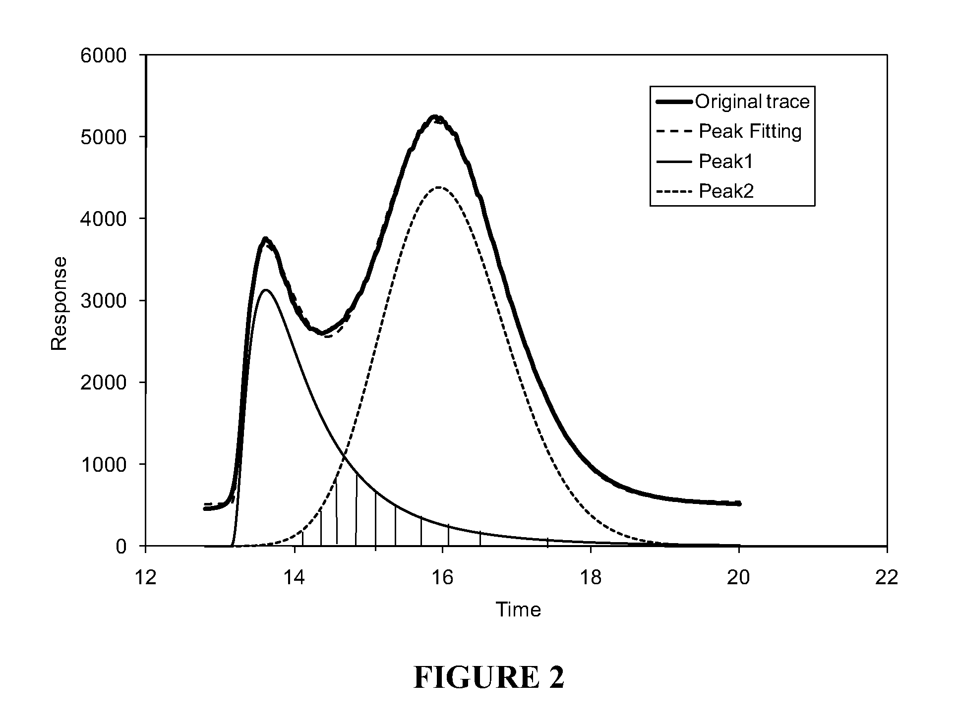
[0103]Peak fitting of the solubility profile.

[0104]A solution of a petroleum product (0.1000 g) was prepared in 10 mL of methylene chloride. The solution was injected into a stainless steel column using the same equipment, solvents and procedure as described in Example 1.

[0105]The asphaltene solubility profile of the sample was recorded using the same equipment and in substantially the same manner as in Example 1.

[0106]The asphaltene solubility profile shown in FIG. 2 and labeled as original trace was processed mathematically so that it was separated into two distinct peaks (i.e., Peak 1 and Peak 2). A personal computer running commercially available software package (GRAMS / AI by Thermo Galactic) was used for carrying out the mathematical procedure. FIG. 2 also shows the curve corresponding to the peak fitting of the original trace curve as well as the curves corresponding to the separated peaks, i.e., Peak 1 and Peak 2. As discussed in Example 1, Peak 1 is referred to as “easy to d...

example 3

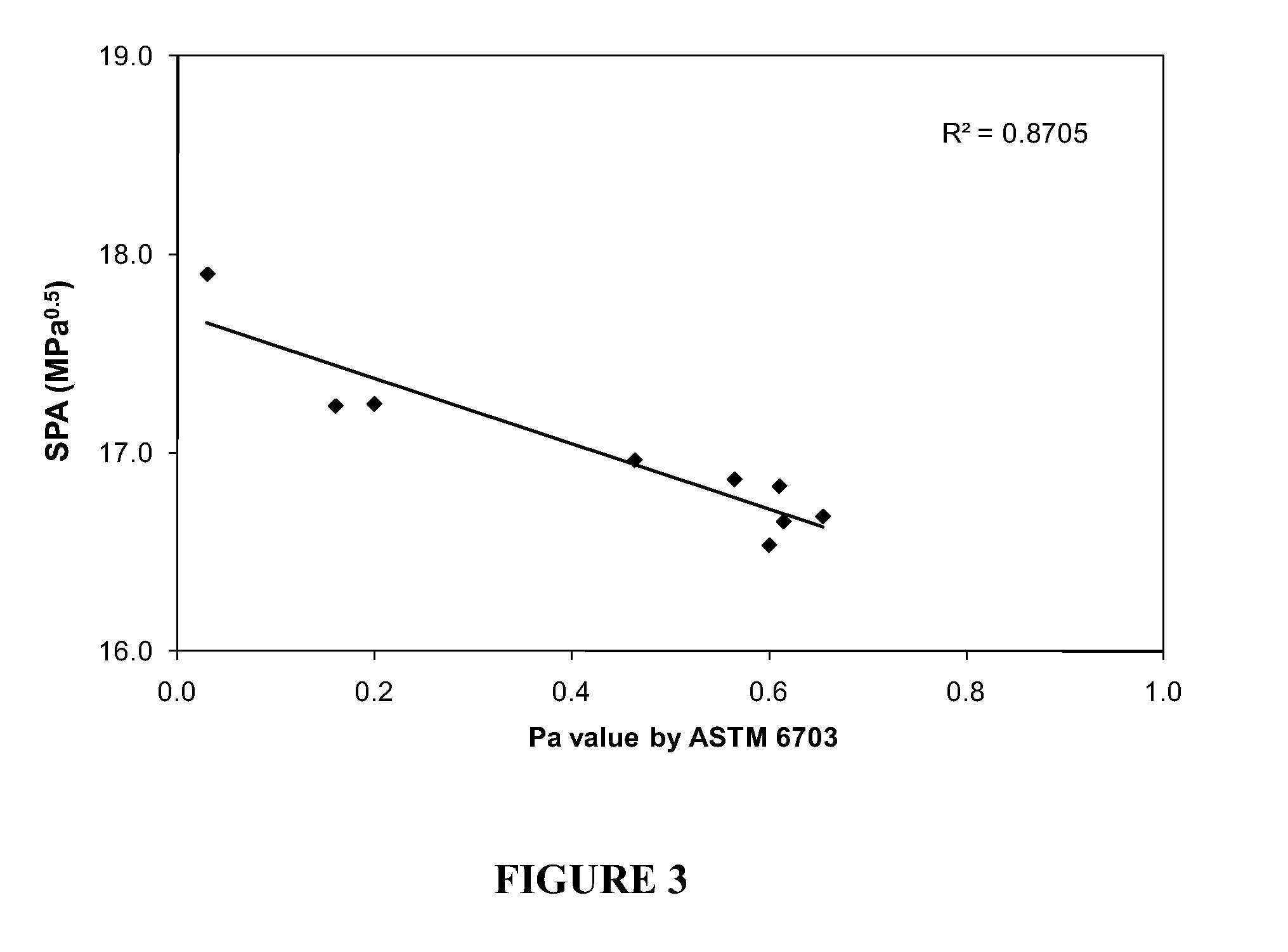
[0108]SPA as a function of the peptizability value determined by ASTM 6703.

[0109]Several solutions of asphaltenes extracted from different hydrocarbon containing materials including virgin (Crude oils and vacuum residues) and processed materials were prepared by dissolving 0.0100 g of asphaltenes in 10 mL of methylene chloride. The solutions were injected into a separate stainless steel column using the same equipment, solvents and procedure as described in Example 1.

[0110]The asphaltene solubility profile of the sample was recorded using the same equipment and in substantially the same manner as in Example 1. The resulting asphaltene solubility profiles were then mathematically processed according to Example 2 using a personal computer running commercially available software package (GRAMS / AI by Thermo Galactic) to obtain the separated peaks. The SPA or average solubility parameter of the hard to dissolve asphaltenes (Peak 2) was determined as the mean of the distribution of respon...


PUM


Abstract

A method for determining asphaltene stability in a hydrocarbon-containing material having solvated asphaltenes therein is disclosed. The method involves the steps of: (a) precipitating an amount of the asphaltenes from a liquid sample of the hydrocarbon-containing material with an alkane mobile phase solvent in a column; (b) dissolving a first amount and a second amount of the precipitated asphaltenes by gradually and continuously changing the alkane mobile phase solvent to a final mobile phase solvent having a solubility parameter at least 1 MPa0.5 higher than the alkane mobile phase solvent; (c) monitoring the concentration of eluted fractions from the column; (d) creating a solubility profile of the dissolved asphaltenes in the hydrocarbon-containing material; and (e) determining one or more asphaltene stability parameters of the hydrocarbon-containing material.

Description

BACKGROUND OF THE INVENTION[0001]1. Technical Field[0002]The present invention generally relates to a method for determining asphaltene stability in a hydrocarbon-containing material.[0003]2. Description of the Related Art[0004]Hydrocarbon materials, such as heavy oils, petroleum residua, coal tars, shale oils, asphalts, or the like can comprise polar core materials, such as asphaltenes, dispersed in lower polarity solvent(s). Intermediate polarity material(s), usually referred to as resin(s), can associate with the polar core materials to maintain a homogeneous mixture of the components.[0005]Refinery processes, including but not limited to, atmospheric or vacuum distillation, visbreaking, hydrocracking, delayed coking, Fluid Coking, Flexicoking, hydrotreatment, delay coker or Eureka process that convert hydrocarbon materials to lighter distillate fuels that require heating for distillation, hydrogen addition, or carbon rejection (coking). However, when using conventional refinery ...

Claims


Application Information

Patent Timeline
IPC IPC(8): C10G31/06C10G31/00G01N30/02
CPCC10G75/00G06Q99/00G01N2030/8854
Inventor ROGEL, ESTRELLAOVALLES, CESARMOIR, MICHAEL
Owner CHEVROU USA INC
Learn More