A method and plant of production of combustible gas using biomass

Inactive Publication Date: 2011-04-07
LIU WENZHEN
View PDF2 Cites 3 Cited by
  • Summary
  • Abstract
  • Description
  • Claims
  • Application Information

AI Technical Summary

Benefits of technology

[0016]1. Stable gasification reaction. During gasification, dry biomass material forms a reduction layer, an oxidation layer, a pyrolysis layer, and a drying layer from top to bottom. In this sequence, material density of these layers increases. This is totally different from traditional gasifying methods in which reduction layer and oxidation layer are under pyrolysis layer and drying layer. In this way, discontinuity between gasifying reaction levels, caving in, and burning-through etc. due to gravity can be avoided. This invention very much favors manufacture of large gasifying plants.
[0017]2. High calorific value of fuel gas and low environmental pollution. Since the reduction layer constantly expands downward during gasification reaction, the levels are stable, and the temperature is maintained at 700° C.˜900° C., so that CO2 generated by pyrolysis layer and oxidation layer is subject to reduction reaction to generate more CO, and tar in flue gas is subject to cracking when passing reduction layer to become combustible gas, so that tar content in fuel gas is greatly lowered, difficulty of subsequent fuel gas pu

Problems solved by technology

In addition, this process requires large investment.
For these reasons, it is very difficult to promote this method in China.
Upper suction type gasifying plant features safe operation, but has disadvantages of high tar content in fuel gas generated, difficult purification, unstable gasification process, and serious environmental pollution etc.
Although the lower suction type gasifying plant features lower tar content, more stable gasifi

Method used


Image

  • A method and plant of production of combustible gas using biomass
  • A method and plant of production of combustible gas using biomass

Examples


embodiment 1

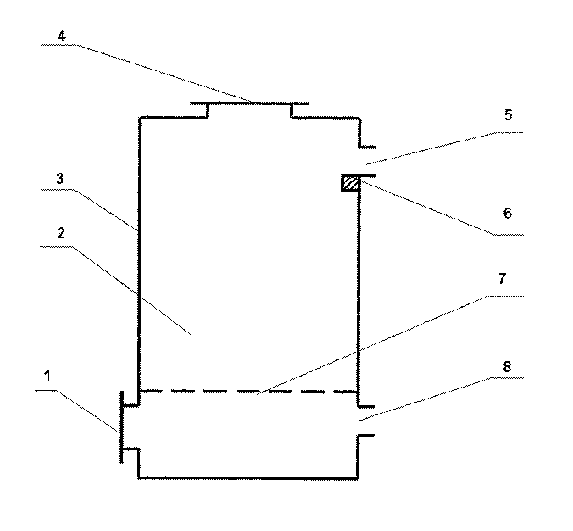
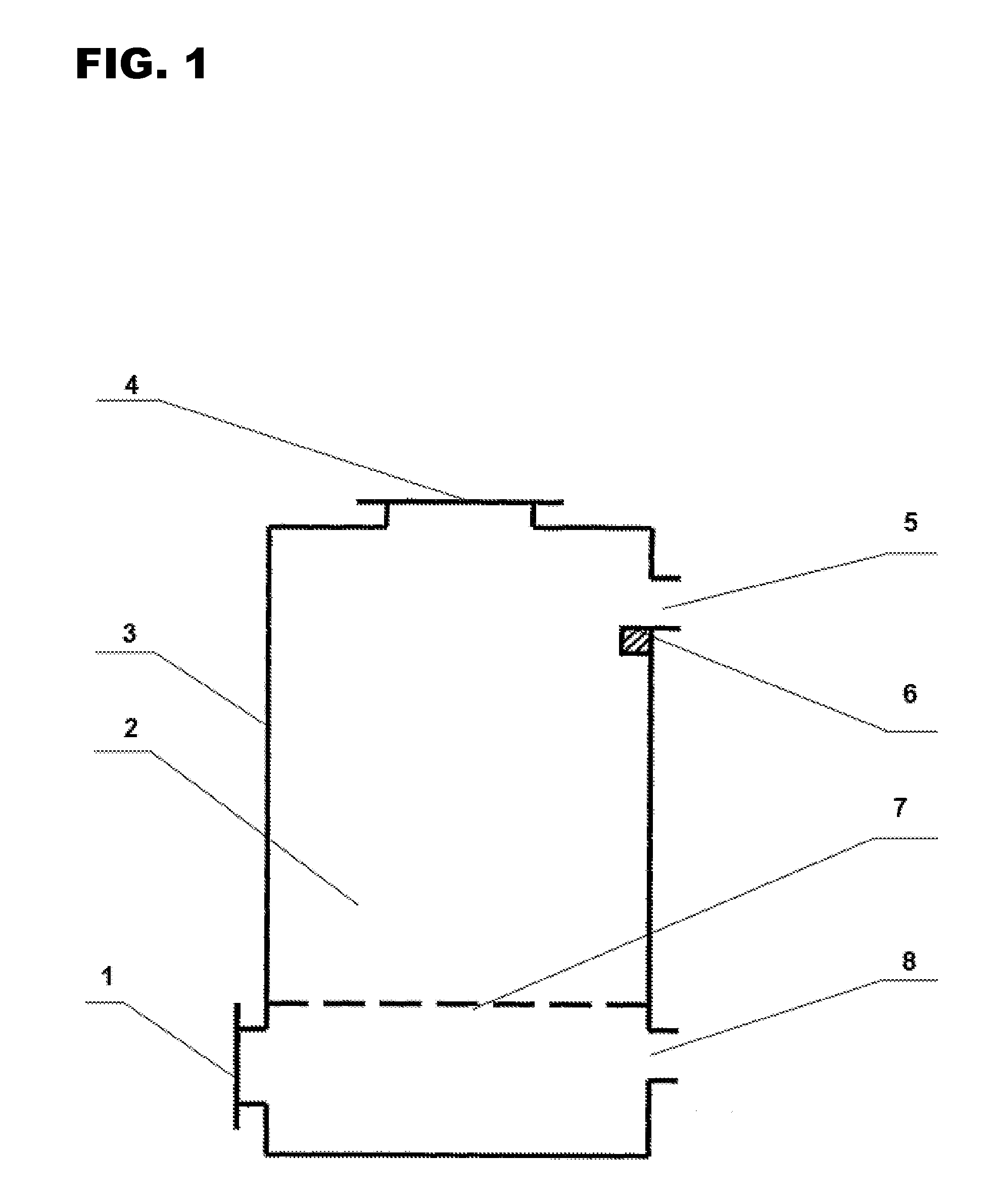
[0024]Preferred Dry biomass material is added into furnace cavity 2 via filling port 4, to the height of fuel gas outlet 5. Fuel gas outlet 5 and air inlet 8 are kept open, while ash discharge port 1 and material filling port are closed. Via ignition device 6, biomass material is ignited and air is blown into furnace cavity 2 via air inlet 8. This air will pass through furnace grate 7 from bottom to top, and go through dry biomass material. At the point of ignition, gasifying agent and dry biomass material will undergo oxidation combustion reaction, to form the oxidation layer of gasifying reaction.

[0025]Under the action of air, the oxidation layer moves from point of ignition at upper part of material down. Since the air first undergoes oxidation combustion reaction with material at lower part of the oxidation layer, upper part material of the oxidation layer gets less and less air for oxidation reaction, gradually forming a reduction layer consisting of hot biomass charcoal above...

embodiment 2

[0027]Preferred Remove furnace grate 7 from furnace cavity 2. Load dry biomass material into furnace cavity 2 via filling port 4, to 10-30 cm higher than fuel gas outlet 5, while making this material in contact with bottom of furnace cavity 2. Keep flue gas outlet 5 and air inlet 8 open, and close ash discharge port 1 and material filling port 4. Via the ignition device 6, ignite biomass material. Blow air into furnace cavity 2 via air inlet 8. This air will move from bottom to top (starting from air inlet 8) to pass dry biomass material. Gasifying agent and dry biomass material undergo oxidation combustion reaction from the point of ignition, forming oxidation layer of gasification reaction.

[0028]Subsequent gasification reaction and gasification reaction levels formed are the same as preferred embodiment 1. The part of the material higher than fuel gas outlet 5 will gradually fall into reduction layer due to reducing volume of material of the underlying reduction layer, oxidation ...


PUM


Abstract

This invention involves a method and plant of production of combustible gas using biomass. This plant comprises a furnace body, a furnace cavity, gasifying agent inlet, combustible gas outlet (arranged on furnace cavity and higher than gasifying agent inlet), and a device that ignites biomass arranged at intersection between the horizontal plane where the combustible gas outlet is located and the internal wall of the furnace cavity. Method of operation: load biomass in the plant and ignite the upper part; gasifying agent will run through the material from bottom to top, gasifying the material and generating flue gas. This invention features outstanding advantages of stable gasifying reaction, safe and reliable operation, high fuel gas calorific value, low environmental pollution, and easy purification of combustible gas etc. This method can be used to produce combustible gas from not only biomass, but also solid organic gasifying raw materials such as household garbage and industrial refuse etc.

Description

FILED OF THE INVENTION[0001]This invention relates to the technology of biomass energy equipment, in particular a method and plant of production of combustible gas using biomass.BACKGROUND OF THE INVENTION[0002]Biomass is a regenerative energy source that features the following: ① regeneration; ② low pollution; ③ wide distribution. Use of biomass as alternative energy source can improve environment, in that acid rain and CO2 in atmosphere can be reduced, thereby has active significance in alleviating the “greenhouse effect”. Volatile content of biomass is as high as above 70%. After being heated, biomass can release large amount of volatile matter at relatively low temperature. Therefore, gasifying technology is very suitable for conversion of biomass raw material. The high grade fuel gas generated by biomass gasification can be directly used as fuel for production and living purposes, and also used for internal combustion engine or gas turbine for power generation, to realize combi...

Claims


Application Information

Patent Timeline
IPC IPC(8): C10J3/72
CPCC10B49/02C10B53/02Y02E50/14C10J2300/0916C10J2300/0956C10J3/20Y02E50/10Y02P20/145
Inventor LIU, WENZHEN
Owner LIU WENZHEN
Why Eureka
Try Eureka