Compositions and Methods for Functionalized Patterning of Tissue Engineering Substrates Including Bioprinting Cell-Laden Constructs for Multicompartment Tissue Chambers

a tissue engineering and cell-laden technology, applied in the field of compositions and methods for tissue engineering substrates including bioprinting cell-laden constructs for multi-compartment tissue chambers, can solve the problems of low mechanical properties of scaffolds, lack of interconnection, and often far from the requirements of tissue engineering scaffolds

Inactive Publication Date: 2011-06-09
DREXEL UNIV
View PDF10 Cites 62 Cited by
  • Summary
  • Abstract
  • Description
  • Claims
  • Application Information

AI Technical Summary

Problems solved by technology

Nevertheless, these technologies are often far from meeting the requirements of tissue engineering scaffolds.
For instance, the solvent casting technique is a relatively easy fabrication process, but the scaffolds have low mechanical properties.
Furthermore, the phase separation technique is able to manufacture scaffolds with high porosity but these scaffolds have lack of interconnectivity.
In general the aforementioned techniques do not offer controlled architecture, with optimum mechanical characteristics, such as porosity and interconnectivity, which are essential for tissue engineered scaffolds.
However, the initial drawback of FDM is that it requires filament preparation which is highly time consuming process.
The unexpected buckling and break in the filament cause the manufacture to stop.
In addition, polycaprolactone is biocompatible and biodegradable and is approved by FDA for numerous medical and drug delivery devices.
However, most currently used biomaterials often lack adequate surface structural or biochemical cues without an additional surface functionalization.
One challenge in scaffold guided tissue engineering is to design and manufacture scaffolds with required mechanical integrity and regulating cellular microenvironment to provide structural, biological, physical and chemical cues to cells.
While proper scaffold manufacturing techniques can offer structural cues through intricate scaffold internal architectures to sustain the mechanical integrity of the cellular environment in vitro, the presence of biological, chemical and physical cues on the scaffolds is often not readily available for some synthesized biopolymer materials (Yildirim et al., 2007, NEBC Bioengineering Conference, IEEE 33rd Annual Northeast, 243-244; Shor et al., 2007, Biomaterials 28(35), 5291-5297; Yildirim et al., 2008, Plasma Processes and Polymers 5:397-397).
Though effective in attracting cells on the patterned surfaces, the preparation of patterned mask and patterned stamps is often costly and requires long processing times and special clean room instrumentation (Hwang et al., 2009, Lab on a Chip 9:167-170; Falconnet et al., 2004, Advanced Functional Materials 14:749-756).
In addition, the harsh chemical and solvent used in the process may also damage the patterned bio-organic layers (Khademhosseini et al., 2007, Biomedical Microdevices 9:149-157; Itoga et al., 2004, Biomaterials 25:2047-2053).
Furthermore, the mask or stamps used do not provide precision control over the degree of surface functionalization, especially when using patterns having complex geometries (Ruiz et al., 2007, Soft Matter 3:168-177; Lee et al., 2003, Bulletin of the Korean Chemical Society 24:161-162).
Existing plasma functionalization techniques do not allow for functionalized patterning on the surface of a substrate material without the use of mask, stamps or chemical treatment.
Further, the current use of chemical coatings and modifications for cell / matrix attachment of microfluidic channels leads to residue formation and subsequent channel occlusions.
Published biological data show that existing in vitro microfluidic devices do not demonstrate good cell viability or preservation of normal in vivo cell-specific physiological function necessary to accurately perform pharmacokinetic studies on a long-term basis.
This system is very expensive to operate and requires a large amount of space in which to operate.
It is impossible to accurately generate physiologically realistic conditions at such a large scale.
One disadvantage of this system is that it relies upon cell migration for cell seeding, with no possibility for direct positional control of cell placement.
However, this method is a 2-D cell patterning of the feeder layer and does not have the ability for 3-D positional control and patterning of cells.
This reference does not describe creating an artificial three dimensional tissue incorporated into a microfluidic device and therefore, it is limited to interactions of cells seeded on the surfaces of the chamber.

Method used


Image

  • Compositions and Methods for Functionalized Patterning of Tissue Engineering Substrates Including Bioprinting Cell-Laden Constructs for Multicompartment Tissue Chambers
  • Compositions and Methods for Functionalized Patterning of Tissue Engineering Substrates Including Bioprinting Cell-Laden Constructs for Multicompartment Tissue Chambers
  • Compositions and Methods for Functionalized Patterning of Tissue Engineering Substrates Including Bioprinting Cell-Laden Constructs for Multicompartment Tissue Chambers

Examples


experimental examples

[0190]The invention is now described with reference to the following Examples. These Examples are provided for the purpose of illustration only and the invention should in no way be construed as being limited to these Examples, but rather should be construed to encompass any and all variations which become evident as a result of the teaching provided herein.

[0191]Without further description, it is believed that one of ordinary skill in the art can, using the preceding description and the following illustrative examples, make and utilize the compounds of the present invention and practice the claimed methods. The following working examples therefore, specifically point out the preferred embodiments of the present invention, and are not to be construed as limiting in any way the remainder of the disclosure.

example 1

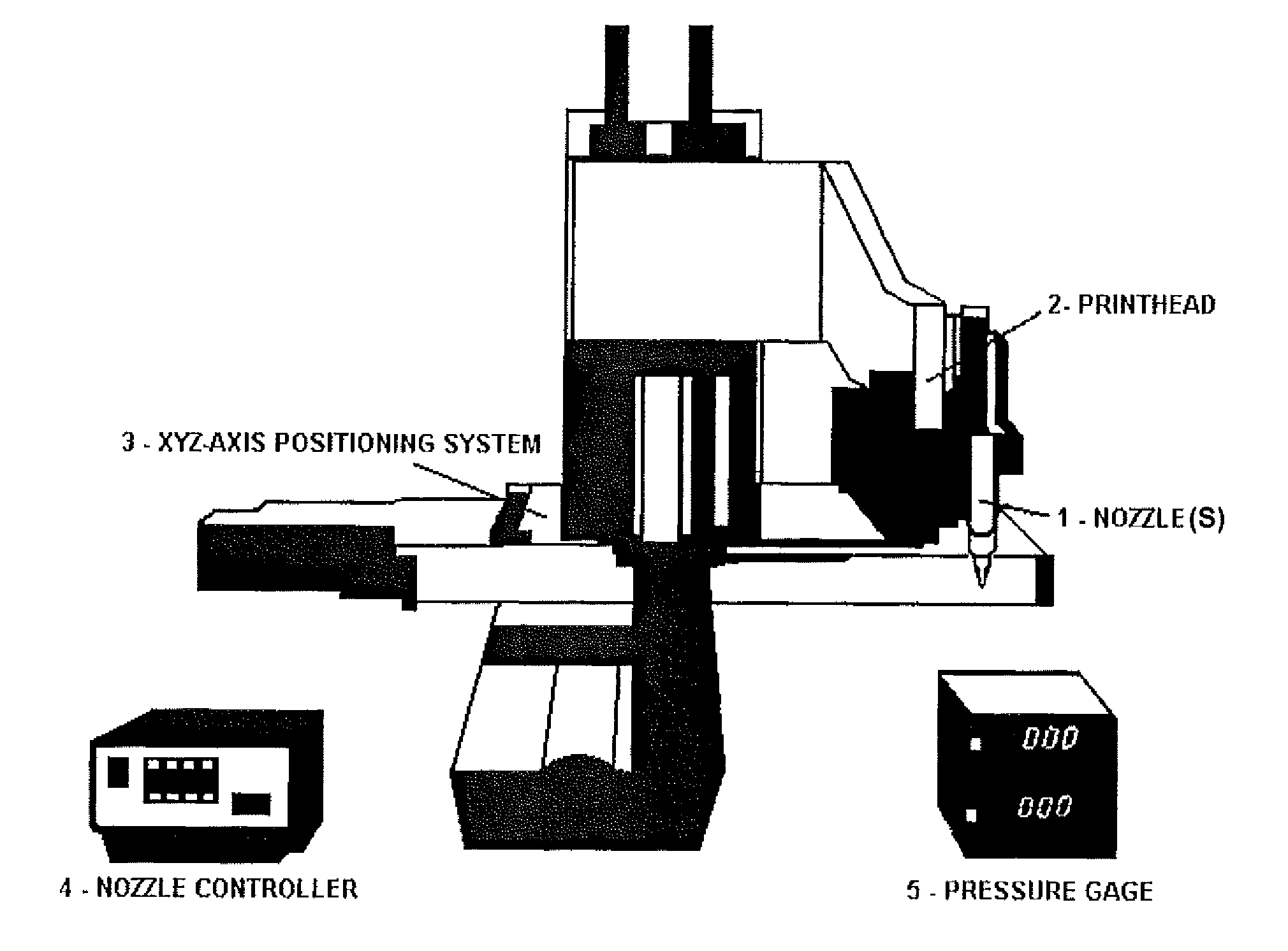
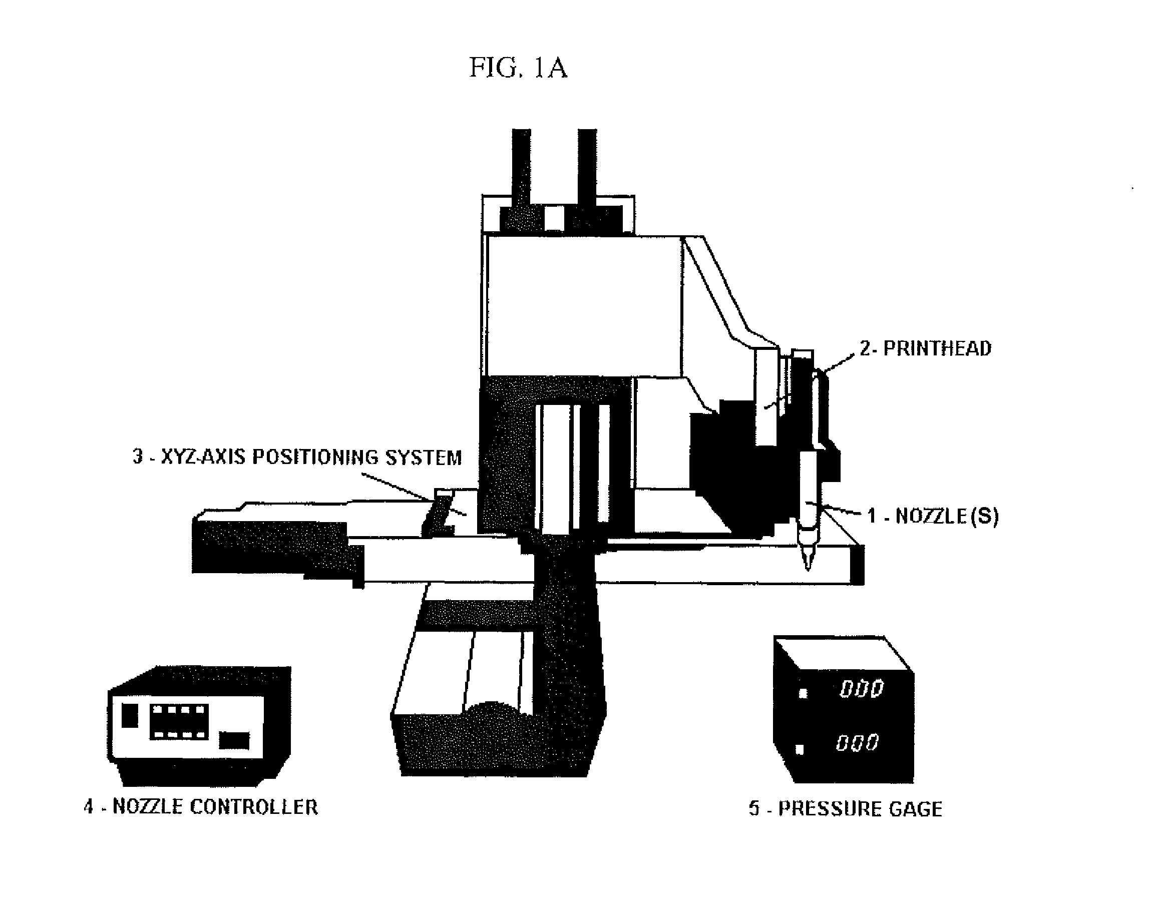
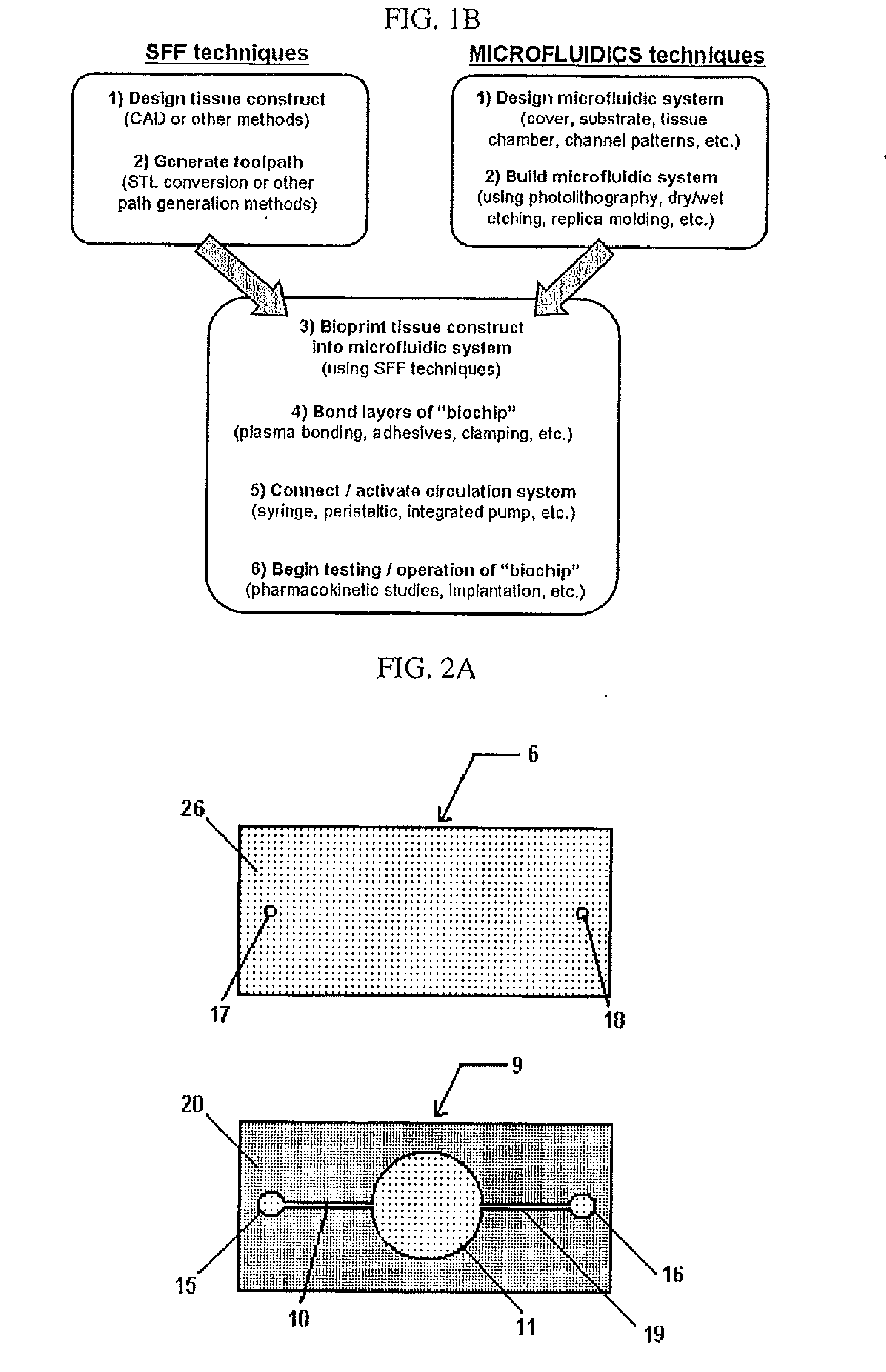
[0192]Human hepatocytes (HepG2) and human melanoma cells (M10) were cultured in α-Minimum Essential Medium (Gibco) at 37° C. in 5% CO2. Cells were mixed with BME (i.e., Basement Membrane Matrix Phenol Red-free (BD Biosciences Matrigel)) chilled to 4° C. and printed onto a glass microfluidic chip having a PDMS substrate (see FIGS. 13 and 14) using a temperature-controlled BME printing apparatus 0-5° C. (see, for example, FIGS. 9 and 10).

[0193]After 24 hours, cells were treated with an inactive form of the anti-radiation drug amifostine (see Grochova, 2007, J Appl Biomed 5:17) by perfusion of a 1 mM solution of the inactive form of amifostine in media for 4 hours. The inactive form of amifostine (i.e., WR-2721; H2N-(CH2)3-NH—(CH2)2-S—PO3H2) is converted to the active form (i.e., WR-1065; H2N—(CH2)3—NH—(CH2)2—SH) when it is dephosphorylated by cells. After the 4 hour treatment with amifostine, the cells were exposed to 2 Grays of γ-radiation from a cesium source. Immediately after expo...

example 2

Plasma Treatment of Polycaprolactone Scaffolds

[0195]This example describes a solid free-form fabrication (SFF) technology based Precision Extrusion Deposition (PED) process for manufacturing manufacture three-dimensional (3D) polycaprolactone scaffolds and their surface treatment with plasma source for enhanced osteoblast cell adhesion and proliferation. The PED process allows the manufacture of tissue engineering scaffolds based on designed geometry with complete interconnectivity, controllable porosity. The as-fabricated polycaprolactone scaffolds have a 0 / 90° strut configuration of 300 μm pore size and 250 μm strut width. In order to improve cellular activity on 3D polycaprolactone scaffolds, they were surface treated with oxygen-based plasma source. The surface hydrophilicity and total surface energy of polycaprolactone was increased with plasma treatment. Comparison was made between different plasma treatment times, including 30 seconds, 1, 2, 3, 5 and 7 minutes to identify the...


PUM

PropertyMeasurementUnit
melting temperatureaaaaaaaaaa
shear stressaaaaaaaaaa
diameteraaaaaaaaaa

Abstract

The present invention relates to microfluidic systems and methods for monitoring or detecting a change in a characteristic of an input substance. Specifically, the invention relates to a model for in vitro pharmacokinetic study and other pharmaceutical applications, as well as other uses including computing, sensing, filtration, detoxification, production of chemicals and biomolecules, testing cell / tissue behavior, toxicology, drug metabolism, drug screening, drug discovery, and implantation into a subject. The present invention also relates to systems and methods of a microplasm functionalized surface patterning of a substrate. The present invention represents an improvement over existing plasma systems used to modify the surface of a substrate, as the present invention creates surface patterning without the use of a mask, stamp or a chemical treatment.

Description

CROSS-REFERENCE TO RELATED APPLICATIONS[0001]This application claims the benefit of priority of U.S. patent application Ser. No. 61 / 238,481, filed Aug. 31, 2009, and U.S. patent application Ser. No. 61 / 258,917, filed Nov. 6, 2009, the entire disclosures of which are incorporated by reference herein as if each is set forth herein in its entirety.STATEMENT REGARDING FEDERALLY SUPPORTED RESEARCH OR DEVELOPMENT[0002]This invention was made with government support under Grant No. 09940-008 awarded by NASA USRA. The U.S. Government has certain rights in the invention.BACKGROUND OF THE INVENTION[0003]Tissue engineering (TE) is an emerging field for tissue repair and regeneration compared to conventional techniques including autograft and allograft, through engineering functional implants created from living cells. TE is a highly interdisciplinary research area where material science, engineering and biology are blended to achieve tissue regeneration (Vacanti, 2007, Proc Am Philos Soc. 151:...

Claims


Application Information

Patent Timeline
Patent Type & Authority Applications(United States)
IPC IPC(8): C12Q1/02C12M1/00C12M1/34C23C16/50C23C16/52
CPCB01L3/502761B01L2300/0877B01L2300/0883B01L2300/0887C12M23/16B01L2400/0418B01L2400/0677B01L2400/086B01L2300/161
Inventor SUN, WEISNYDER, JESSICACHANG, ROBERTYILDIRIM, EDAFRIDMAN, ALEXANDERAYAN, HALIM
Owner DREXEL UNIV
Why Eureka
Try Eureka