Fabrication of substrates with a useful layer of monocrystalline semiconductor material

Inactive Publication Date: 2011-07-14
S O I TEC SILICON ON INSULATOR THECHNOLOGIES
View PDF20 Cites 35 Cited by
  • Summary
  • Abstract
  • Description
  • Claims
  • Application Information

AI Technical Summary

Benefits of technology

[0032]In aspects of this embodiment, the material and the thickness of the nucleation layer are selected so that thermal expansion of the support substrate and of the working layer occurs without significant damage; the semiconductor material layer is epitaxially deposited on the nucleation layer and the nucleation layer

Problems solved by technology

Semiconductor technology based on the use of GaN, AlN, and compounds thereof as semiconductor material, currently suffer from a lack of large-sized bulk substrates of such materials.
However, sapphire and silicon carbide are far from being optimal substrate material due to their lattice parameters and their expansion coefficients.
Although these substrate materials are often selected for their small lattice mismatch and their similar coefficient of expansion with GaN, they suffer from having poor chemical stability under high temperatures as compared to sapphire or silicon carbide.
Furthermore, once the layer or layers intended to form the substrate have been formed, in the majority of cases the support on which growth has been carried out has to be removed, which necessitates either chemical attack of said support and thus its loss even if it is produced from an expensive material, thereby increasing the c

Method used


Image

  • Fabrication of substrates with a useful layer of monocrystalline semiconductor material
  • Fabrication of substrates with a useful layer of monocrystalline semiconductor material
  • Fabrication of substrates with a useful layer of monocrystalline semiconductor material

Examples


example 1

[0081]A 500 nm thick layer of SiO2 is produced on one face of a monocrystalline SiC source substrate by thermal oxidation. Hydrogen ions are then implanted with an energy of 100 keV and using a dose of 8×10¹⁶ ions / cm2 into the source substrate using ion bombardment equipment. A 500 μm thick monocrystalline GaAs substrate intended to form the intermediate support is also prepared, and one face of the substrate is coated with a 500 nm thick SiO2 layer by chemical vapor deposition.

[0082]Surface activation is then carried out, for example by chemical-mechanical polishing, to smooth the surfaces and provide them with a certain hydrophilic nature. The faces of the source substrate and the intermediate support substrate are then brought together and bonded, and a suitable bonding energy is obtained by heat treatment at 350° C. for a period of 2 hours.

[0083]This assembly then undergoes heat treatment at 900° C. for a period of one hour to obtain detachment at the implanted zone. The face of...

example 2

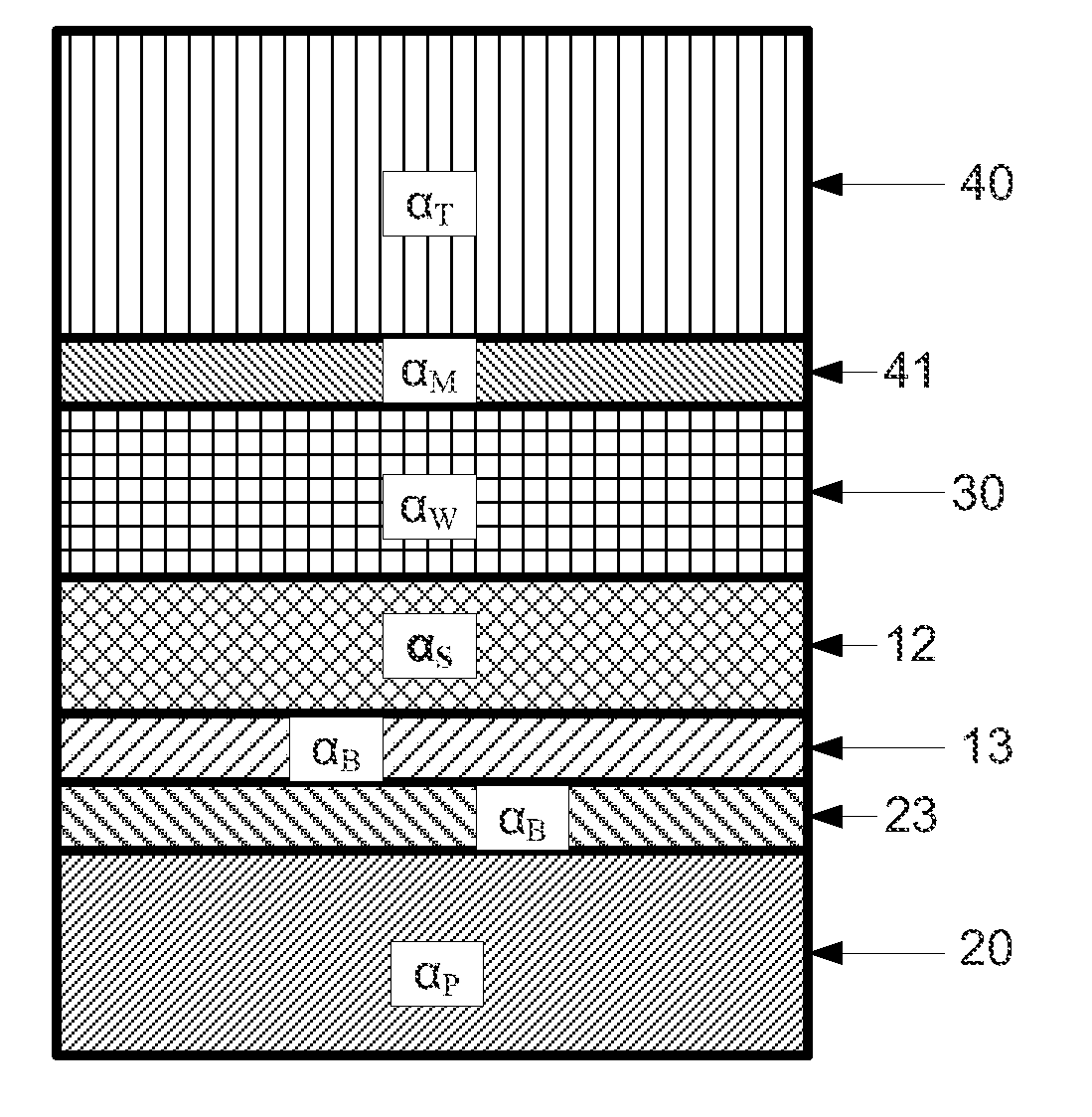
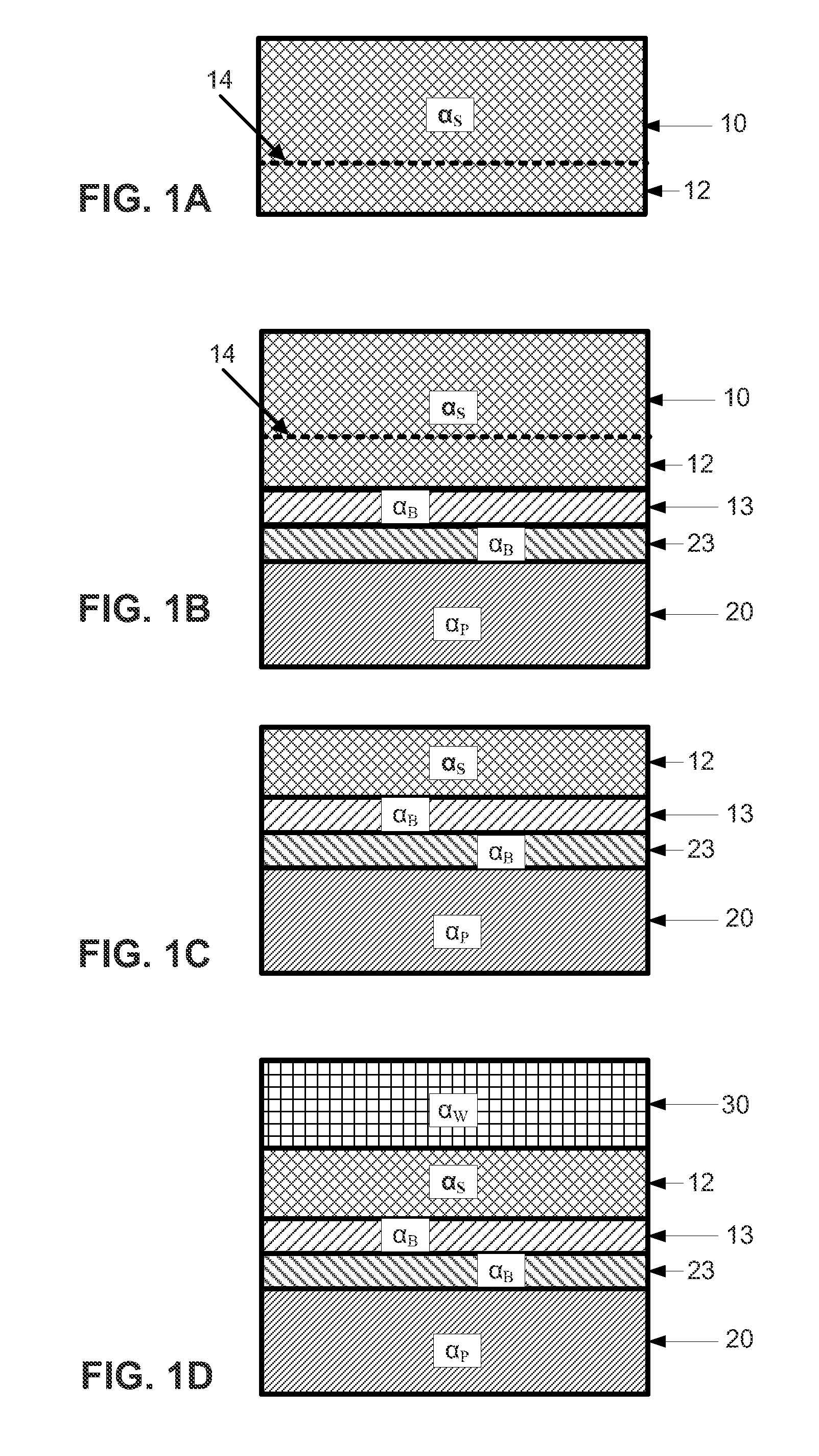
[0087]In accordance with another aspect of the invention, referring to FIGS. 2A to 2E, the technique includes transferring a nucleation layer or seed layer 12 onto a support substrate 20 (illustrated in FIG. 2C), depositing a semiconductor layer or working layer 30 on the seed layer 12 to form a composite substrate (illustrated in FIG. 2D), and then detaching the seed layer 12 and the working layer 30 from the composite substrate (illustrated in FIG. 2E). The seed layer in accordance with this aspect of the invention may comprise material such as sapphire, silicon carbide, zinc oxide, silicon, gallium nitride, neodymium gallate, lithium gallate, or any combination thereof. Also included are other materials commonly known in the art. In an implementation, the seed layer 12 is prepared before receiving the working layer, wherein the preparation may include polishing, annealing, smoothing, oxidation, etching or any combination thereof.

[0088]Preferably the material comprising the seed l...

example 3

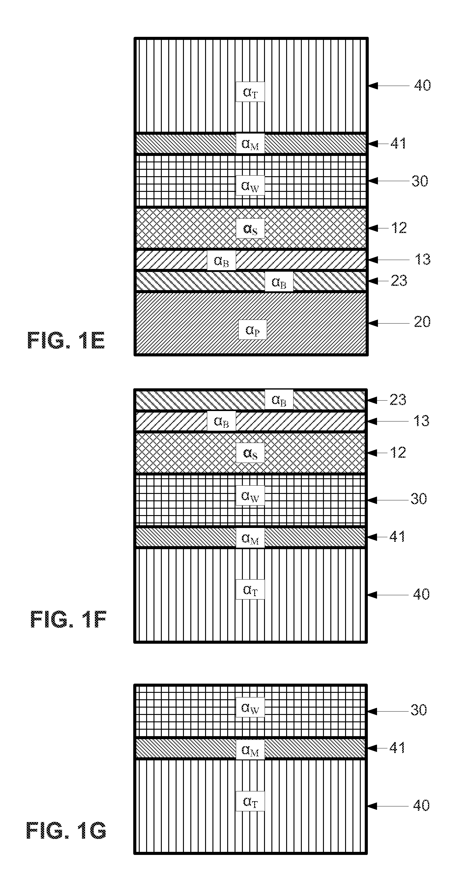
[0095]In another embodiment of the method of the invention, a structure is provided comprising a working layer on a seed layer itself on a support with bonding layers and interposed between the seed layer and the support. A thick layer is deposited on the free surface of the working layer and the support is removed, either alone or together with the seed layer. The thick layer then serves in particular to support the working layer, after the seed layer support has been removed.

[0096]In this embodiment, the further layer of the substrate is present upon the working layer on a face opposite that of the seed layer, wherein the further layer preferably is polycrystalline SiC, polycrystalline AlN, polycrystalline GaN, boron nitride, diamond or a metal such a copper.

[0097]Table 2 below summarizes examples of materials that can be used in the context of this second implementation of the method of the invention. These examples are purely illustrative and should not be construed as limiting....


PUM


Abstract

The invention relates to methods for fabricating a semiconductor substrate. In one embodiment, the method includes transferring a seed layer on to a support substrate; and depositing a working layer on the seed layer to form a composite substrate. The seed layer is made of a material that accommodates thermal expansion of the support substrate and of the working layer. In another embodiment, the method includes providing a source substrate with a weakened zone defining a nucleation layer, bonding a support substrate to the source substrate, detaching the nucleation layer and support substrate at the weakened zone by applying laser irradiation stress, depositing a semiconductor material upon the nucleation layer, bonding a target substrate to the deposited layer and removing the support substrate and nucleation layer. The result is a semiconductor substrate that includes the layer of semiconductor material on a support or target substrate.

Description

CROSS-REFERENCE TO RELATED APPLICATIONS[0001]This application is a continuation-in-part of application Ser. No. 11 / 831,484 filed Jul. 31, 2007, which is a division of application Ser. No. 10 / 883,437 filed on Jul. 1, 2004, now U.S. Pat. No. 7,265,029, which is (a) a continuation of application Ser. No. 10 / 458,471 filed on Jun. 9, 2003, abandoned, and (b) a continuation-in-part of application Ser. No. 10 / 446,605, filed on May 27, 2003, now U.S. Pat. No. 6,794,276, which is a continuation of International application no. PCT / FR01 / 03714 filed Nov. 26, 2001. The entire content of each prior application is expressly incorporated herein by reference thereto.FIELD OF THE INVENTION[0002]The present invention relates to methods of fabricating a semiconductor substrate. In an embodiment, the semiconductor substrate includes at least one layer of monocrystalline semiconductor material, especially a wide band gap material, and in particular a mono or poly-metallic nitride substrate, such as gall...

Claims


Application Information

Patent Timeline
IPC IPC(8): H01L21/30
CPCH01L21/76254H01L21/187H01L21/185
Inventor LETERTRE, FABRICEGHYSELEN, BRUNORAYSSAC, OLIVIERRAYSSAC, PIERRERAYSSAC, GISELE
Owner S O I TEC SILICON ON INSULATOR THECHNOLOGIES
Why Eureka
Try Eureka