Catalytic materials for fuel cell electroded and method for their production

a fuel cell and electroded technology, applied in the field of catalytic materials, can solve the problems of reducing the performance of the fuel cell, reducing the proton conductivity of the membrane, and reducing the mass transfer, so as to achieve high electron conductivity, low catalyst loading, and high performance

Inactive Publication Date: 2011-09-01
NAT RES COUNCIL OF CANADA
View PDF10 Cites 20 Cited by
  • Summary
  • Abstract
  • Description
  • Claims
  • Application Information

AI Technical Summary

Benefits of technology

[0029]In accordance with the invention, there is provided a catalyst layer structure which basically constitutes a layer or a bilayer of catalytic material for use in an electrode in an MEA in a fuel cell, particularly in a proton exchange membrane fuel cell (PEMFC), said catalytic material being deposited in-situ by Reactive Spray Deposition Technology (RSDT) directly onto PEM substrate, said catalytic material layer either containing interspersed electrically conducting support particles (typically carbon particles) offering catalyst support, or being support-free. The catalytic layer comprises predominantly catalyst particles sized between 1 and 15 nm, the catalyst layer structure providing high electron conductivity, and in a fuel cell arrangement, a relatively high performance measured by power output and voltage of the fuel cell at a relatively low catalyst loading. Typically, the catalytic layer structure provides a PEM fuel cell performance above about 0.6 W / cm2 at a catalyst loading of 0.1 mg / cm2 or less.

Problems solved by technology

The presence of excess water in the catalyst layer can block gas transport, leading to reduced mass transfer and decreased fuel cell performance.
On the other hand, a lack of water results in decreased proton conductivity of the membrane and the ionomer in the catalyst layers, leading to decreased fuel cell performance.
In general, higher Pt loading leads to better performance, but it also results in higher cost, which is one of the key factors hindering PEM fuel cell commercialization.
Inkjet printing demonstrated the capacity to control ink volume for low catalyst loading however fuel cell testing on the fabricated CLs did not show any performance advantages [Towne, S., Viswanathan, V., Holbery, J., and Rieke, P. Fabrication of polymer electrolyte membrane fuel cell MEAs utilizing inkjet print technology.
Another substantial disadvantage of ink-based CL fabrication relates to poor capacity to control and optimize micro-, meso- and macro-structure of CL during its formation on a support or membrane and at the hot-pressing step.
There are contradictory results in the literature related to optimizing CL performance, due to the complexity induced by proton and electron conduction, reactant and product mass transport, as well as electrochemical reactions within the CL.
Additionally, the ink prepared by mixing a carbon supported platinum with Nafion and possibly other surfactants and then spraying limits the achievable film thickness to 1 μm.
The minimum thickness of a single ink spray coated layer is about 1 micron, which makes this method not applicable for fabrication of thin graded CLs with ultra-low catalyst loading.
Carbon suffers from weak corrosion resistance in fuel cell operating conditions.
However, current methods for fabrication of unsupported CLs have substantial disadvantages hindering commercial application of such CL material.
The application of the modified thin film method, despite its relatively higher Pt utilization, to micro-PEMFC applications has proven ineffective due to relatively higher Pt loadings.
Although electrocatalysts fabricated by the electrodeposition method achieved the highest Pt utilization, the application of this method to large-scale manufacturing is doubtful due to concerns regarding its scalability.
However, the low Pt utilization, non-controlled porosity and poor substrate adherence of the Pt remain challenges.
This assumption is not always valid because a change of any operating condition causes appropriate amendment to requirements for a CL and needs optimization of its design, structure and composition.
The known approaches do not provide PEMFC developers with alternative catalytic materials adjusted and optimized to specific operation conditions.

Method used


Image

  • Catalytic materials for fuel cell electroded and method for their production
  • Catalytic materials for fuel cell electroded and method for their production
  • Catalytic materials for fuel cell electroded and method for their production

Examples


example 1

Unsupported Platinum Catalyst Layer

[0117]A variant of the RSDT method allows the deposition of a catalyst layer without support or ionomer directly onto a polymer substrate i.e. a membrane.

[0118]FIG. 4a shows a transmission electron microscope (TEM) image of 100 nm thick unsupported platinum catalyst layer deposited by RSDT onto a Nafion® membrane using only the primary reactant comprising a catalyst material (platinum in this case) in the deposition process.

[0119]FIG. 4b shows a TEM image of bi-layer structure of the catalyst layer comprising an ultra-thin (with 45-90 nm thickness) dense unsupported Pt layer disposed directly on the membrane and a uniformly distributed supported catalyst layer disposed on the top of the unsupported CL; primary reactant comprising a catalyst material (platinum in this case) initially deposited (thin black line in upper left corner) followed by a second layer comprising primary (platinum in this case), secondary (carbon) and tertiary (a perfluorosulf...

example 2

Confirmation of Platinum Composition and Phase

[0134]XRD analysis was carried out to investigate the phase composition of the catalyst coatings produced by RSDT. Substrates include both reference inorganic substrates and organic polymer substrates to get clear spectra and eliminate possible interferences.

[0135]Coatings on amorphous (glass) and crystalline (mono-crystalline Si wafer) inorganic substrates covered the deposition temperature range of 100-220 C, which is typical for depositions on polymer substrates. Results clearly show the presence of polycrystalline Pt phase, regardless of substrate nature and over the entire temperature range (FIG. 13).

[0136]XRD spectrum of Pt layer coated on organic polymer substrate are shown in FIG. 14. Pt pattern is clearly visible. The strong intensity of the Pt (111) diffraction peak relative to the rest of the pattern indicates that RSDT unsupported catalyst layer exhibits a preferential (111) orientation of Pt crystallites.

XPS Examination

[0137...

example 3

Deposition of Ternary Composite—Platinum, Carbon and Ionomer Based on Perfluorosulfonic Acid

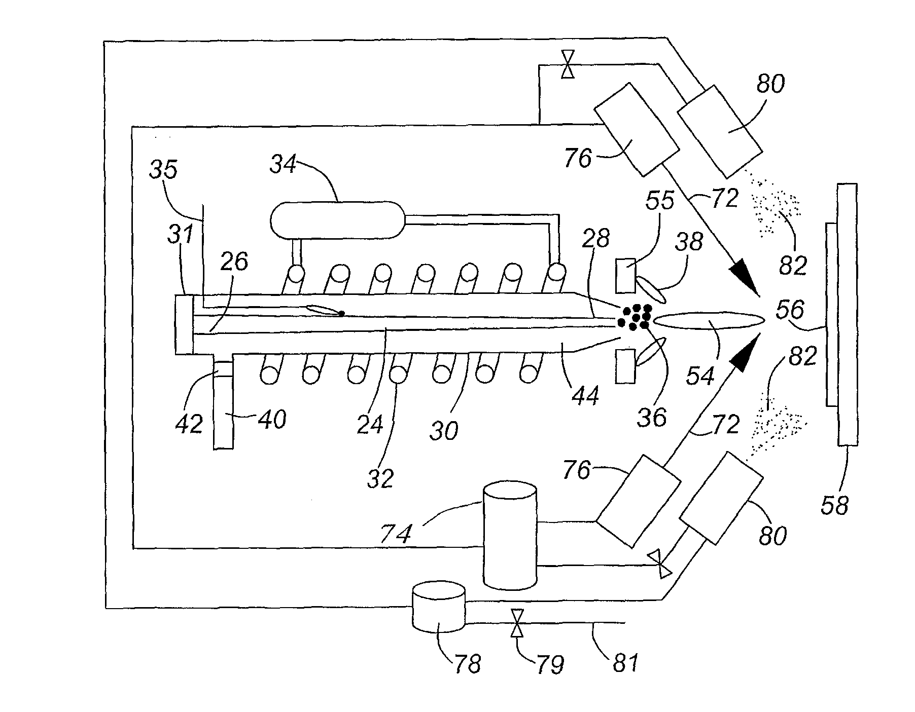
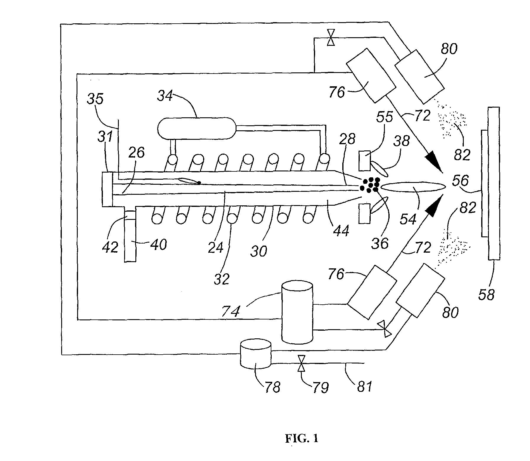
[0148]Following the procedures listed for platinum-only depositions and modifying the process a binary composite solution can be added to the platinum flame plume to produce a supported uniformly distributed ternary composite CL. Using a secondary set of commercially available spray nozzles (EFD-inc.), we introduce the binary component at angles of 80-30° relative to the flame centerline. The binary mixture is formed by mixing given ratios of carbon powder (such as Vulcan XC-72R) and a perfluorosulfonic acid in a suitable solvent, sonicating the mixture and spraying directly into the gas plume containing Pt particles.

[0149]The flux rate of the carbon / ionomer solution and platinum metal are decoupled in this process. Very specific platinum to carbon ratios can be achieved simply by fixing the starting concentration of either platinum or carbon. Likewise, the ionomer composition can also be adj...


PUM

PropertyMeasurementUnit
sizeaaaaaaaaaa
thicknessaaaaaaaaaa
thicknessaaaaaaaaaa

Abstract

Layered catalyst structures for fuel cells, particularly for a Proton Exchange Membrane Fuel Cell (PEMFC), are produced by a reactive spray deposition technology process. The catalyst layers so produced contain particles sized between 1 and 15 nm and clusters of such particles of a catalyst selected from the group consisting of platinum, platinum alloys with transition metals, mixtures thereof and non-noble metals. The catalyst layers without an electrically conducting supporting medium exhibit dendritic microstructure, providing high electrochemically active surface area and electron conductivity at ultra-low catalyst loading. The catalyst layers deposited on an electrically conducting medium, such as carbon, exhibit three-dimensional functional grading, which provides efficient utilization as a catalyst, high PEMFC performance at the low catalyst loading, and minimized limitations caused by reactant diffusion and activation. The catalytic layers may be produced by a single-run deposition method.

Description

CROSS-REFERENCE TO RELATED APPLICATIONS[0001]This application claims benefit of U.S. Provisional Patent Application U.S. Ser. No. 60 / 193,240 filed Nov. 7, 2008, the entire contents of which are herein incorporated by reference.TECHNICAL FIELD[0002]This invention relates to catalytic materials and in particular to catalyst layer structures for electrodes in membrane electrode assemblies (MEAs) for Proton Exchange Membrane Fuel Cells (PEMFC). The invention further relates to a method for manufacturing the catalytic materials.BACKGROUND ART[0003]In a fuel cell, a catalyst layer (CL) is located between the proton exchange membrane (PEM) and the gas diffusion layer (GDL). Protons transfer between the CL and the PEM, and electrons transfer between the catalyst layer and the GDL. All these elements require good interfacial contact. In a PEM fuel cell, the CLs are where the electrochemical reactions occur for electric power generation. For example, for H2 / air (O2) PEM fuel cells, the reacti...

Claims


Application Information

Patent Timeline
Patent Type & Authority Applications(United States)
IPC IPC(8): H01M4/92B01J37/12B01J37/08B01J37/02B01J27/02B01J23/42B82Y30/00B82Y40/00
CPCH01M4/8642H01M4/8668H01M4/8673H01M4/886H01M4/92Y10S977/948H01M4/926H01M4/96H01M2008/1095Y02E60/50Y10S977/754H01M4/921
Inventor ROLLER, JUSTINMARIC, RADENKAFATIH, KHALIDNEAGU, ROBERTO
Owner NAT RES COUNCIL OF CANADA
Why Eureka
Try Eureka