Surface-coated cutting tool

a cutting tool and surface coating technology, applied in manufacturing tools, superimposed coating processes, transportation and packaging, etc., can solve the problems of easy chipping (fine chipping) on the cutting edge, the life of the coated tool is approaching the end of its usable life, and the high temperature strength and surface properties of the hard coating layer are not adequate, etc., to achieve excellent high temperature hardness and heat resistance, excellent high-temperature strength, and enhanced strength within the crystal grains

Active Publication Date: 2012-01-05
MITSUBISHI MATERIALS CORP
View PDF5 Cites 25 Cited by
  • Summary
  • Abstract
  • Description
  • Claims
  • Application Information

AI Technical Summary

Benefits of technology

[0043]Since the surface-coated cutting tool of the present invention has the configuration described above, the ratio of the (0001) plane orientation is high in the intermediate layer composed of the reformed α-type Al2O3 layer. As a result, the surface-coated cutting tool has excellent high-temperature strength, in addition to excellent high-temperature hardness and heat resistance. In addition, by increasing the ratio of the (0001) plane orientation in the upper layer composed of the reformed layer, the upper layer obtains the texture made of crystal grains having flat-plate polygonal shape (including flat hexagonal) at the top and bottom, and elongated shape at sides with surface flatness. Moreover, in the upper layer, strength within the crystal grains is enhanced by forming ...

Problems solved by technology

However, when this conventional coated tool is used for high-speed intermittent cutting work of high-hardness steel, such as quenching materials for alloy tool steel or bearing steel, the high-temperature strength and surface properties of the hard coating layer are not adequate.
Thus, chipping (fine chipping) occurs easily on the cutting edge.
As a result, under such conditions, the coated tool comes to the end of its usable lifespan in a relatively short period of time.
In addition, when the conventional coated tool is used ...

Method used


Image

  • Surface-coated cutting tool
  • Surface-coated cutting tool
  • Surface-coated cutting tool

Examples


first embodiment

[0076](a) The conventional α-type Al2O3 layer in the conventional coated tool 1 is vapor-deposited, for example, using a normal chemical vapor deposition apparatus under the following conditions.

[0077]Composition of reaction gas: in vol. %, 6 to 10% of AlCl3, 10 to 15% of CO2, 3 to 5% of HCl, 0.05 to 0.2% of H2S, and H2 as balance

[0078]Reaction atmosphere temperature: 1020 to 1050° C.

[0079]Reaction atmosphere pressure: 3 to 5 kPa

[0080]On the other hand, the α-type Al2O3 layer in the present invention corresponding to the intermediate layer 12B is formed, using a normal chemical vapor deposition apparatus under the following conditions.

[0081]Composition of reaction gas: in vol. %, 3 to 10% of AlCl3, 0.5 to 3% of CO2, 0.01 to 0.3% of C2H4, and H2 as balance

[0082]Reaction atmosphere temperature: 750 to 900° C.

[0083]Reaction atmosphere pressure: 3 to 13 kPa

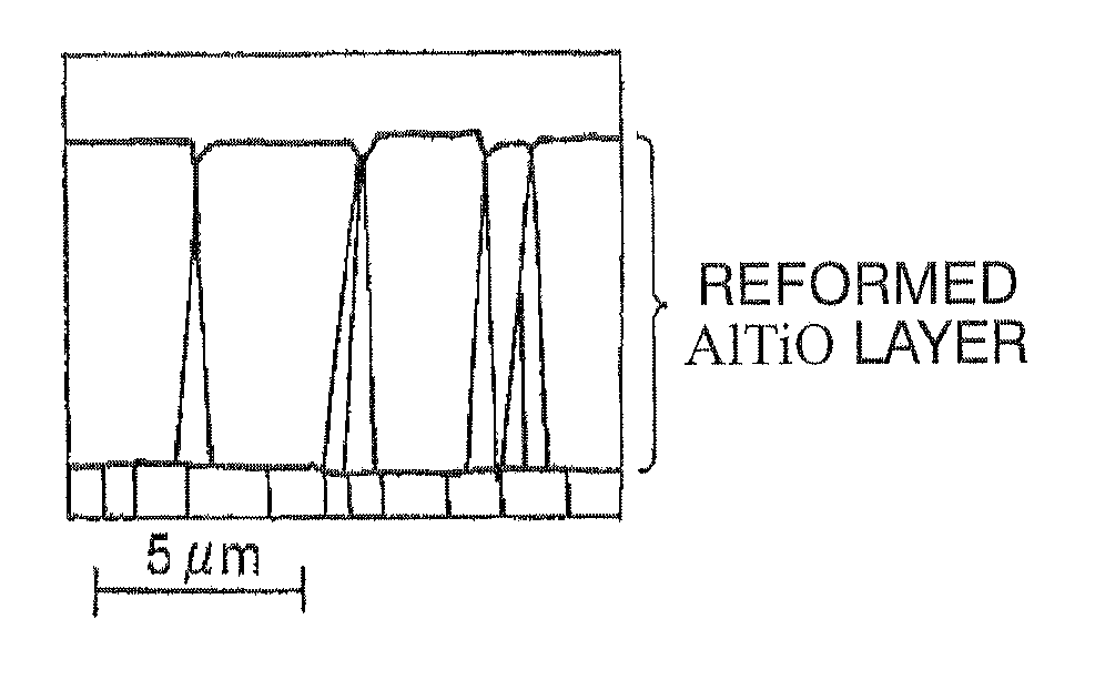
[0084]An Al2O3 neclear is formed on the surface of a Ti compound layer which is the lower layer 12A under the low-temperature condit...

second embodiment

[0171]A coated tool of the second embodiment of the present invention has the following configuration.

[0172](a) The conventional α-type Al2O3 layer in the conventional coated tool 1 is vapor-deposited, for example, using a normal chemical vapor deposition apparatus under the following conditions.

[0173]Composition of reaction gas: in vol. %, 6 to 10% of AlCl3, 10 to 15% of CO2, 3 to 5% of HCl, 0.05 to 0.2% of H2S, and H2 as balance

[0174]Reaction atmosphere temperature: 1020 to 1050° C.

[0175]Reaction atmosphere pressure: 3 to 5 kPa

[0176]In the second embodiment, an Al2O3 neclear is formed on the surface of a Ti compound layer, which is a lower layer, using a standard chemical vapor deposition apparatus under the following low-temperature conditions: composition of reaction gas, in vol. %, 3 to 10% of AlCl3, 0.5 to 3% of CO2, 0.01 to 0.3% of C2H4, and H2 as balance; reaction atmosphere temperature, 750 to 900° C.; reaction atmosphere pressure, 3 to 13 kPa.

[0177]An Al2O3 neclear is form...

third embodiment

[0266]A third embodiment of the present invention includes the following aspects.

[0267](a) The conventional α-type Al2O3 layer in the conventional coated tool 1 is vapor-deposited, for example, using a normal chemical vapor deposition apparatus under the following conditions.

[0268]Composition of reaction gas: in vol. %, 6 to 10% of AlCl3, 10 to 15% of CO2, 3 to 5% of HCl, 0.05 to 0.2% of H2S, and H2 as balance

[0269]Reaction atmosphere temperature: 1020 to 1050° C.

[0270]Reaction atmosphere pressure: 3 to 5 kPa

[0271]On the other hand, the α-type Al2O3 layer in the present invention corresponding to the intermediate layer is formed, using a normal chemical vapor deposition apparatus under the following low-temperature conditions.

[0272]Composition of reaction gas: in vol. %, 3 to 10% of AlCl3, 0.5 to 3% of CO2, 0.01 to 0.3% of C2H4, and H2 as balance

[0273]Reaction atmosphere temperature: 750 to 900° C.

[0274]Reaction atmosphere pressure: 3 to 13 kPa

[0275]In this case, it is desirable tha...


PUM

PropertyMeasurementUnit
Lengthaaaaaaaaaa
Lengthaaaaaaaaaa
Lengthaaaaaaaaaa

Abstract

A surface-coated cutting tool includes a tool substrate made of tungsten carbide-based cemented carbide or titanium carbonitride-based cermet; and a hard coating layer formed by vapor-depositing in order, a lower layer (a), an intermediate layer (b), and an upper layer (c) on the tool substrate. The lower layer (a) is a Ti layer composed of one or more of a titanium carbide layer, a titanium nitride layer, a titanium carbonitride layer, a titanium carboxide layer, and a titanium oxycarbonitride layer, and having a thickness of 3 to 20 μm. The intermediate layer (b) is an aluminum oxide layer having a thickness of 1 to 5 μm, and having an α-type crystal structure in a chemically vapor-deposited state. The upper layer (c) is an aluminum oxide layer having a thickness of 2 to 15 μm, and containing one or more elements of Ti, Y, Zr, Cr, and B.

Description

TECHNICAL FIELD[0001]The present invention relates to a surface-coated cutting tool (hereinafter referred to as a coated tool) which exhibits excellent cutting performance over the long-term, without the hard coating layer becoming chipped, for example, (1) if cutting work on high-hardness steel, such as quenching materials for alloy tool steel or bearing steel, is performed under high-speed intermittent cutting conditions where intermittent impact loading repeatedly acts on the cutting edge, along with the accompanying high heat generation, or (2) if cutting work on difficult-to-cut materials, such as stainless steel or ductile cast iron, is performed under high-speed heavy cutting conditions where a high load resulting from a high feed rate and a high depth of cut act on the cutting edge, along with the accompanying high heat generation.[0002]This application claims priority on Japanese Patent Application No. 2009-065814 filed on Mar. 18, 2009, Japanese Patent Application No. 2009...

Claims


Application Information

Patent Timeline
IPC IPC(8): B23B27/14
CPCC23C16/0272C23C16/30C23C16/32C23C16/34C23C16/36Y10T428/24975C23C16/403C23C30/005C23C28/042C23C28/044Y10T428/265C23C16/40
Inventor TOMITA, KOHEIIGARASHI, MAKOTOOSADA, AKIRANAKAMURA, EIJI
Owner MITSUBISHI MATERIALS CORP
Why Eureka
Try Eureka