Powder magnetic core

Active Publication Date: 2012-04-05
TDK CORPARATION
5 Cites 38 Cited by

AI-Extracted Technical Summary

Problems solved by technology

However, in a powder magnetic core fabricated using iron powder which has been subjected to an insulating treatment such as a phosphate treatment, since the heat resistance of a phosphoric acid coating is low, the core resistance is likely to be reduced by a heat treatment of 600° C. or higher and eddy-current loss increases, and as a result, the core loss cannot be sufficiently reduced.
However, if a compacting pressure is increased in order to increase the density of the core, force acting on particles and on the interface between the particles increases, and thus the insulating layers are destroyed or peeled off, which results in a reduction in an electrical...

Method used

[0038]The thickness of the insulating layer of the core particle 2 is not particularly limited, but is preferably about from 5 to 500 nm. With the thickness within this range, required insulation property and high magnetic permeability tend to be easily ensured.
[0041]Components constituting the inner layer 3a are not particularly limited, examples of which may include various kinds of known metals and the oxides thereof. However, the inner layer 3a preferably contains the iron oxide and at least one kind of an oxide of nonferrous metal. With the configuration in which the iron oxide is contained not only in the outermost layer 3b but also in the inner layer 3a, magnetic properties such as magnetic permeability tend to be further increased. In addition, with the configuration in which iron is contained as a common metal in the insulating passivation layer 3, adhesiveness between the layers (the inner layer 3a and the outermost layer 3b) tends to increase, and thus more uniform coating can be achieved. Furthermore, with the configuration in which the oxide of nonferrous metal is contained, the electrical resistance of the insulating passivation layer can be further enhanced.
[0043]The content of nonferrous metal in the inner layer 3a is not particularly limited, but the content of nonferrous metal in the inner layer 3a is preferably from 5 to 80 at. %, more preferably from 5 to 60 at. %, and even more preferably from 10 to 40 at. %, based on an element content analysis by TEM-EDS analysis excluding C and O. By setting the content to 5 at. % or higher, the heat resistance and insulation property tend to be further improved, while by setting the content to 80 at % or lower, the adhesiveness and magnetic permeability of the coatings tend to be further improved.
[0044]The components constituting the inner layer 3a may include carbon, nitrogen, fluorine, other residues, etc. in addition to those listed above. However, the content of carbon, nitrogen, fluorine and other residues is preferably low in order to improve magnetic properties. These components may be produced as a result of a heat treatment performed on the later-described soft magnetic material or may exist in the form of oxides, etc.
[0045]The thickness of the inner layer 3a is not particularly limited; however, in general, the thickness is preferably from 50 nm to 1.0 μm. By setting the thickness of the inner layer 3a to 50 nm or more, the electrical resistivity of the resulting powder magnetic core tends to be enhanced, while by setting the thickness of the inner layer 3a to 1.0 μm or lower, magnetic properties such as the density of magnetic flux and magnetic permeability tend to be enhanced.
[0047]In the components constituting the outermost layer 3b, the content of Fe element in the outermost layer 3b is preferably 50 at. % or more, and more preferably 70 at. % or more, based on an element content analysis by TEM-EDS analysis excluding C and O. With a large amount of iron oxide contained as the main component, the adhesiveness between the layers in the insulating passivation layer 3 and performance to fill gaps of the layers in the insulating passivation layers 3 tend to be further improved, and the density of magnetic flux can be further enhanced. In the related art, core particles are coated using silane coupling agents or silicone resins. Although such a technique can enhance the electrical resistivity to a certain degree, it has a problem in that the density of magnetic flux is greatly lowered. On the other hand, in the composite magnetic particle I of the present embodiment, since the outermost layer 3b of the insulating passivation layer 3 contains the iron oxide as the main component, the powder magnetic core having high electrical resistivity and high magnetic flux density can be achieved.
[0048]The components constituting the outermost layer 3b may further include carbon, nitrogen, fluorine, other residues, etc, in addition to the iron oxide. However, the content of carbon, nitrogen, fluorine and other residues is preferably low in order to improve magnetic properties. These components may be produced as a result of a heat treatment performed on the soft magnetic material as described below or may exist in the form of oxides, etc.
[0049]The thickness of the outermost layer 3b is not particularly limited; however, in general, the thickness is preferably from 10 nm to 500 nm. By setting the thickness of the outermost layer 3b to 10 nm or more, the adhesiveness between particles in the resulting powder magnetic core tends to be enhanced, while by setting the thickness of the outermost layer 3b to 500 nm or less, the density of magnetic flux and the density of compaction tend to be enhanced.
[0056]An organic ligand of the metal complex contained in the coating layer of the raw powder (soft magnetic material) may employ a ligand constituted by C, H, O, F, etc. By using the coating layer containing such an organic ligand, the coating layer having excellent heat resistance and coating formability can be formed. In addition, in the heat treatment step described below, reaction of metal such as iron contained in the raw powder (soft magnetic material) can be effectively promoted between the layers. As a result, coatings having high adhesiveness, large thickness and high uniformity can be efficiently formed.
[0058]A preferable metal complex contained in the coating layer of the raw powder (soft magnetic material) may be a metal chelate complex having a central metal and at least one chelate ligand. By using a metal chelate complex that is stable due to the chelating effect, a coating layer having excellent heat resistance and coating formability can be formed. Another preferable metal complex may be a metal chelate complex having a central metal and a plurality of chelate ligands.
[0064]When the metal complex is applied, a mixing process may be performed as needed using a kneader, a mixer, a stirrer, a granulator, a disperser, or the like. In addition, in terms of improvements in the uniformity and adhesiveness of the coating layer, it is preferable to employ a spray process in which an application liquid with the metal complex dispersed or dissolved in a solvent is sprayed and applied onto the core particle using a spray gun or the like. Example...

Benefits of technology

[0016]Here, it is preferable that the core particle has a soft magnetic particle containing iron as the main component and an insulating layer formed on a surface of the soft magnetic particle. Since the soft magnetic particle coated with the insulating layer effectively serves as a core particle having an insulation property, a powder magnetic core having high performance can be achieved.
[0017]In the configuration above, the insulating layer of the core particle preferably contains iron phosphate. By coating the soft magnetic particle with the insulating layer containing iron phosphate, even higher heat resistance can be provided.
[0018]The inner layer preferably contains iron oxide and at least one kind of an oxide of nonferrous metal. With the configuration in which not only the outermost layer but also the inner layer contains the iron oxide, the magnetic properties such as magnetic permeability tend to be further improved. In addition, with the configuration in which both the outermost layer and the inner layer contain iron, the adhesiveness ...

Abstract

A powder magnetic core having a high electrical resistivity and a high magnetic flux density, including at least a composite magnetic particle the composite magnetic particle including: a core particle containing iron as the main component; and an insulating passivation layer formed on the core particle, wherein: the insulating passivation layer at least has an inner layer formed on the core particle and the outermost layer formed on the inner layer; and the outermost layer contains iron oxide as the main component.

Application Domain

Technology Topic

Image

  • Powder magnetic core
  • Powder magnetic core
  • Powder magnetic core

Examples

  • Experimental program(7)

Example

Example 1
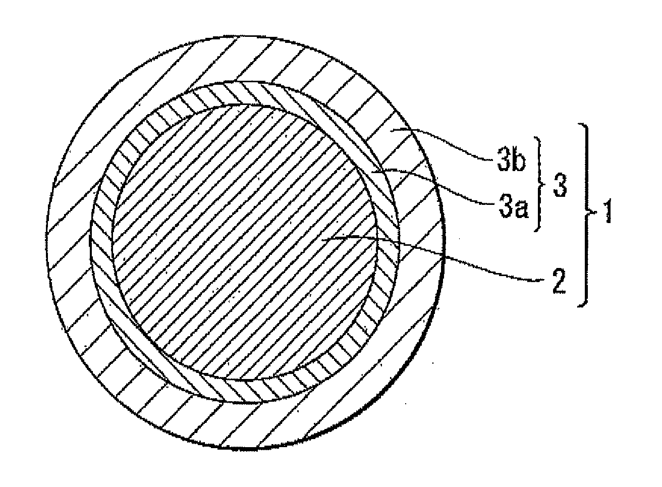
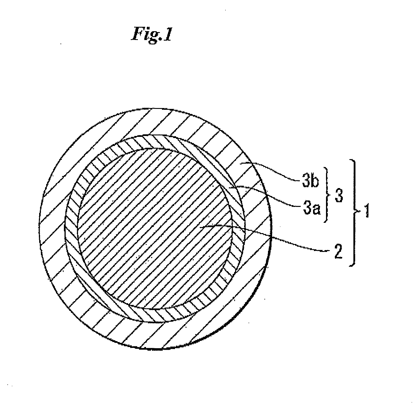
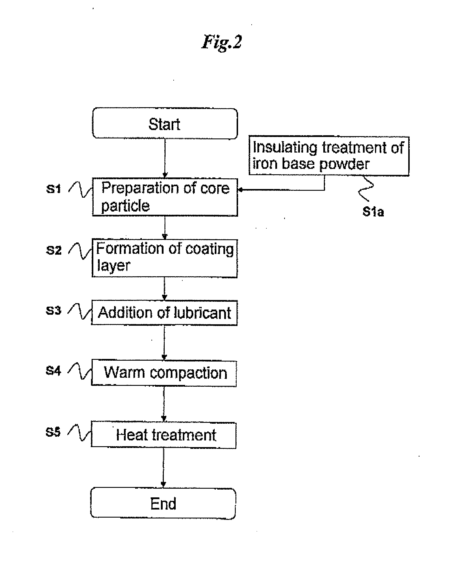
[0076]First, as a core particle having: a soft magnetic particle containing iron as the main component; and an insulating layer formed on the surface of the soft magnetic particle, pure iron coated with an insulating layer (trade name “Somaloy 700” manufactured by Höganäs A B; the average particle diameter: 200 μm) was prepared. Next, solutions obtained by dissolving aluminum isopropoxide and zirconium tetra-normal-propoxide in toluene and a solution obtained by dissolving iron(III) acetylacetonate in toluene were prepared. Then the Al alkoxide solution and the Zr alkoxide solution were applied to the pure iron coated with the insulating layer in the ratios of Al atomic weight of 0.0035 mol % and Zr atomic weight of 0.0035 mol %, respectively, with respect to the Fe atomic weight contained in the soft magnetic particle, and then dried by heating. Then the Fe complex solution was further applied in the ratio of Fe atomic weight of 0.01 mol % with respect to the Fe atomic weight contained in the soft magnetic particle, and then dried by heating to obtain raw powder (soft magnetic material).
[0077]Then 0.1% by mass zinc stearate was added as a lubricant to the raw powder (soft magnetic material), and the resulting mixture was placed in a mixer (trade name “V-blender manufactured by TSUTSUI SCIENTIFIC INSTRUMENTS CO., LTD.) and blended with the revolution speed of 12 rpm for 10 minutes. The blended mixture (blended product) was then subjected to warm-compaction under the condition where the compaction temperature was 130° C. and the compaction pressure was 081 MPa, thereby forming a toroidal core (compact) having the size of 17.5 mm (outer diameter)×10 mm (inner diameter)×4 mm (thickness). Then a heat treatment at 550° C. under the switched atmospheres of nitrogen and the air to obtain a powder magnetic core.
[0078]The structure of the resulting powder magnetic core was checked by TEM observation. In this TEM observation, an observation sample was prepared by a micro-sampling method using Dual-BeamFIB (Nova 200). After preparing the sample, a composition analysis was performed by an EDS (Electron Dispersive x-ray Spectroscopy) using HD 2000 manufactured by Hitachi Ltd, at an acceleration voltage of 200 kV under the following conditions—beam diameter: 1 nm, objective lens aperture diameter: 40 μm, and measurement points: about 30 to 35 points at regular intervals on the interface between particles. FIG. 3 is a schematic diagram showing measurement points in the TEM measurement. As shown in FIG. 3, the measurement points were measured sequentially from the inside of a given particle A to the inside of an adjacent particle B of the powder magnetic core, and the component composition thereof was analyzed. FIG. 4 is a graph showing the component composition of the powder magnetic core in Example 1. As shown in FIG. 4, it has been verified that the powder magnetic core in Example 1 included a core particle containing iron as the main component and insulating passivation layer, and the insulating passivation layer had a two-layer structure constituted by an inner layer containing iron oxide and oxide of nonferrous metal and the outermost layer containing iron oxide as the main component, and the core particle was coated with a phosphoric acid coating.

Example

Example 2
[0079]First, as a core particle having: a soft magnetic particle containing iron as the main component; and an insulating layer formed on the surface of the soft magnetic particle, pure iron coated with an insulating layer (trade name “Somaloy 700” manufactured by Höganäs A B; the average particle diameter: 200 μm) was prepared. Next, a solution obtained by dissolving aluminum isopropoxide in toluene and a solution obtained by dissolving iron(III) acetylacetonate in toluene were prepared. Then the Al alkoxide solution and the Fe complex solution were applied to the pure iron coated with the insulating layer in the ratios of Al atomic weight of 0.0035 mol % and Fe atomic weight of 0.02 mol %, respectively, with respect to the Fe atomic weight contained in the soft magnetic particle, and then dried by healing. Then the Fe complex solution was further applied in the ratio of Fe atomic weight of 0.01 mol % with respect to the Fe atomic weight contained in the soft magnetic particle and then dried by heating to obtain raw powder (soft magnetic material).
[0080]Then 0.1% by mass zinc stearate was added as a lubricant to the raw powder (soft magnetic material), and the resulting mixture was placed in a mixer (trade name “V-blender manufactured by TSUTSUI SCIENTIFIC INSTRUMENTS CO., LTD.) and blended with the revolution speed of 12 rpm for 10 minutes. The blended mixture (blended product) was then subjected to warm-compaction under the condition where the compaction temperature was 130° C. and the compaction pressure was 981 MPa, thereby forming a toroidal core (compact) having the size of 17.5 mm (outer diameter)×10 mm (inner diameter)×4 mm (thickness). Then a heat treatment was performed at 550° C. under the switched atmospheres of nitrogen and the air to obtain a powder magnetic core.

Example

Example 3
[0081]First, as a core particle having: a soft magnetic particle containing iron as the main component; and an insulating layer formed on the surface of the soft magnetic particle, pure iron coated with an insulating layer (trade name “Somaloy 700” manufactured by Höganäs A B; the average particle diameter; 200 μm) was prepared. Next, solutions obtained by dissolving aluminum isopropoxide and zirconium tetra-normal-propoxide in toluene and a solution obtained by dissolving iron(III) acetylacetonate in toluene were prepared. Then the Al alkoxide solution, the Zr alkoxide solution and the Fe complex solution were applied to the pure iron coated with the insulating layer in the ratios of Al atomic weight of 0.0035 mol %, Zr atomic weight of 0.0035 mol %, and Fe atomic weight of 0.02 mol %, respectively, with respect to the Fe atomic weight contained in the soft magnetic particle, and then dried by heating. Then the Fe complex solution was further applied in the ratio of the Fe atomic weight of 0.01 mol % with respect to the Fe atomic weight contained in the soft magnetic particle and then dried by heating to obtain raw powder (soft magnetic material).
[0082]Then 0.1% by mass zinc stearate was added as a lubricant to the raw powder (soft magnetic material), and the resulting mixture was placed in a mixer (trade name “V-blender” manufactured by TSUTSUI SCIENTIFIC INSTRUMENTS CO., LTD.) and blended with the revolution speed of 12 rpm for 10 minutes. The blended mixture (blended product) was then subjected to warm-compaction under the condition where the compaction temperature was 130° C. and the compaction pressure was 981 MPa, thereby forming a toroidal core (compact) having the size of 17.5 mm (outer diameter)×10 mm (inner diameter)×4 mm (thickness). Then a heat treatment was performed at 550° C. under the switched atmospheres of nitrogen and the air to obtain a powder magnetic core.
[0083]The structure of the resulting powder magnetic core was checked by TEM observation. FIG. 5 is a graph showing the component composition of the resulting powder magnetic core. As shown in FIG. 5, it has been verified that the powder magnetic core of Example 3 included the core particle containing iron as the main component and the insulating passivation layer, and the insulating passivation layer had a two-layer structure constituted by an inner layer containing iron oxide and oxide of nonferrous metal and the outermost layer containing a large amount of iron oxide as the main component, and the core particle was coated with a phosphoric acid coating.

PUM

PropertyMeasurementUnit
Thickness5.0E-8m
Thickness1.5E-6m
Magnetic flux density1683000.0μT
tensileMPa
Particle sizePa
strength10

Description & Claims & Application Information

We can also present the details of the Description, Claims and Application information to help users get a comprehensive understanding of the technical details of the patent, such as background art, summary of invention, brief description of drawings, description of embodiments, and other original content. On the other hand, users can also determine the specific scope of protection of the technology through the list of claims; as well as understand the changes in the life cycle of the technology with the presentation of the patent timeline. Login to view more.

Similar technology patents

Movable magnet for magnetically guided catheter

Owner:ST JUDE MEDICAL ATRIAL FIBRILLATION DIV

Infrared frequency comb methods, arrangements and applications

Owner:THE BOARD OF TRUSTEES OF THE LELAND STANFORD JUNIOR UNIV

Classification and recommendation of technical efficacy words

  • High performance
  • High heat resistance

Biodegradable high performance hydrocarbon base oils

InactiveUS6096940AHigh performanceSuperiorRefining to change hydrocarbon structural skeletonHydrocarbon by hydrogenationWaxSolvent
Owner:EXXON RES & ENG CO
Why Eureka
Try Eureka