
Segmented thermoelectric module with bonded legs

a thermoelectric module and leg technology, applied in the field of thermoelectric modules, can solve the problems of mica, marginal strength, easy cracking, and low thermal conductivity of thermoelectric systems, and achieve the effect of efficient application and low thermal conductivity

Inactive Publication Date: 2012-05-03
BASF SE & HI Z TECH
View PDF7 Cites 24 Cited by
  • Summary
  • Abstract
  • Description
  • Claims
  • Application Information

AI Technical Summary

Benefits of technology

[0021]The present invention provides a fully bonded, segmented, long-life, low-cost, mid-temperature to high-temperature, high-efficiency thermoelectric module. Preferred embodiments include a multi-segment, egg-crate module with N legs and P legs that are segmented into at least two segments of thermoelectric materials. In preferred embodiments the segments are chosen for their figure of merit in the various temperature ranges between the hot side and the cold side of the module. In preferred embodiments a low-temperature egg-crate, molded from a liquid crystal polymer material, having relatively very low thermal conductivity holds the legs in place and provides insulation and permits electrical connections for the thermoelectric N legs and P legs to be efficiently applied at the cold side of the module. A castable ceramic capable of operation at temperatures in excess of 500° C. is used to provide electrical insulation between the legs at the hot side of the module. In preferred embodiments the high-temperature ceramic is Resbond 989 or Resbond 908 which is available as a high-temperature, general purpose ceramic adhesive from Cotronix Corporation, and the liquid crystal polymer material is Zenite available from DuPont in the form of a liquid crystal polymer resin. In preferred embodiments the module is sealed in an insulating capsule or a number of modules are sealed together in a thermoelectric generator. All of the parts of the module a solidly bonded together is the preferred module fabrication process so that external pressure is not necessary to assure good contacts within the module.
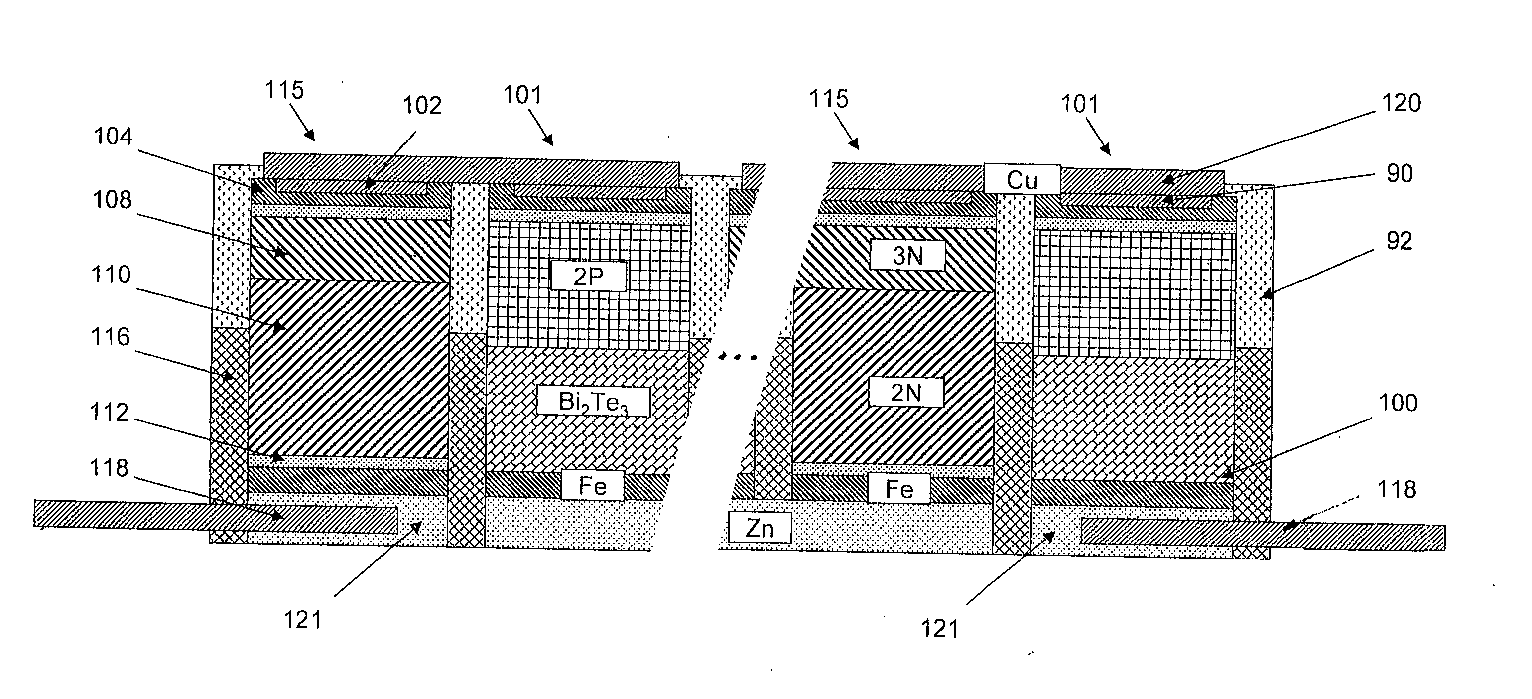
[0022]In a preferred embodiment the N legs are comprised of two types of PbTe and the P legs are comprised of PbTe on the hot side and BiTe on the cold side. To fabricate the legs for this preferred embodiment, iron contacts are vacuum hot pressed along with the thermoelectric materials to create good compatible contact surfaces. Interfaces between the materials are graduated to improve performance. Special techniques are utilized to assure fines are removed. A thin copper binding layer is also added on top of the iron at the hot side of the legs and hot pressed into the leg material. A dual egg-crate is provided with high temperature ceramic used at the hot side and low thermal conductivity moldable thermo plastic is used for the cold side. To fabricate the legs a molybdenum sulfide lubricant is applied to all surfaces of the hot pressing die and plungers to minimize or eliminate leg damage during removal from the die. Tungsten or molybdenum disulfide could also be used as the lubricant.
[0024]The two or three segment legs are produced using a vacuum hot pressed powder metallurgy process in which the leg materials are added to a multi-cavity molybdenum die and hot pressed simultaneously. First a thin layer of iron powder is inserted into the cavity. Then the two or three thermoelectric materials are sequentially added. Iron metal powder is then mixed with lead telluride powder and added at the hot end of each of the P and N legs to provide a one millimeter thick graded layer of PbTe and iron powder. On top of the graded layer a thin layer of 100 percent iron metal layer of powder is added to form the top of the legs. Then the leg powders are then hot pressed at 7,000 psi and 600° C. The iron layer at the top of the legs chemically isolates the PbTe from a copper layer which is added during a centering step following the hot press. The purpose of the thin copper layer is to aid in the bonding of a copper conductor which connects the N and P legs at the hot side electrically in series.
[0026]With a Bi2Te3 segment on the cold side of the PbTe leg it is possible to use Applicants' employer's standard prior art Bi2Te3 contacting methods as described in U.S. Pat. No. 5,856,200, especially FIGS. 19A and 19B and related text, which is incorporated by reference herein. This method is a method of forming contacts to Bi2Te3 using metallic thermal spraying process. The resultant cold side contact is firmly bonded to the legs and eliminates the need to make numerous individual electrical connections. Preferred metallization schemes include: (1) pure zinc, (2) a two-layer system using pure molybdenum as a bond coating and pure aluminum as the electrical and thermal conductor layer.Multi-Cavity Molybdenum Die

Problems solved by technology

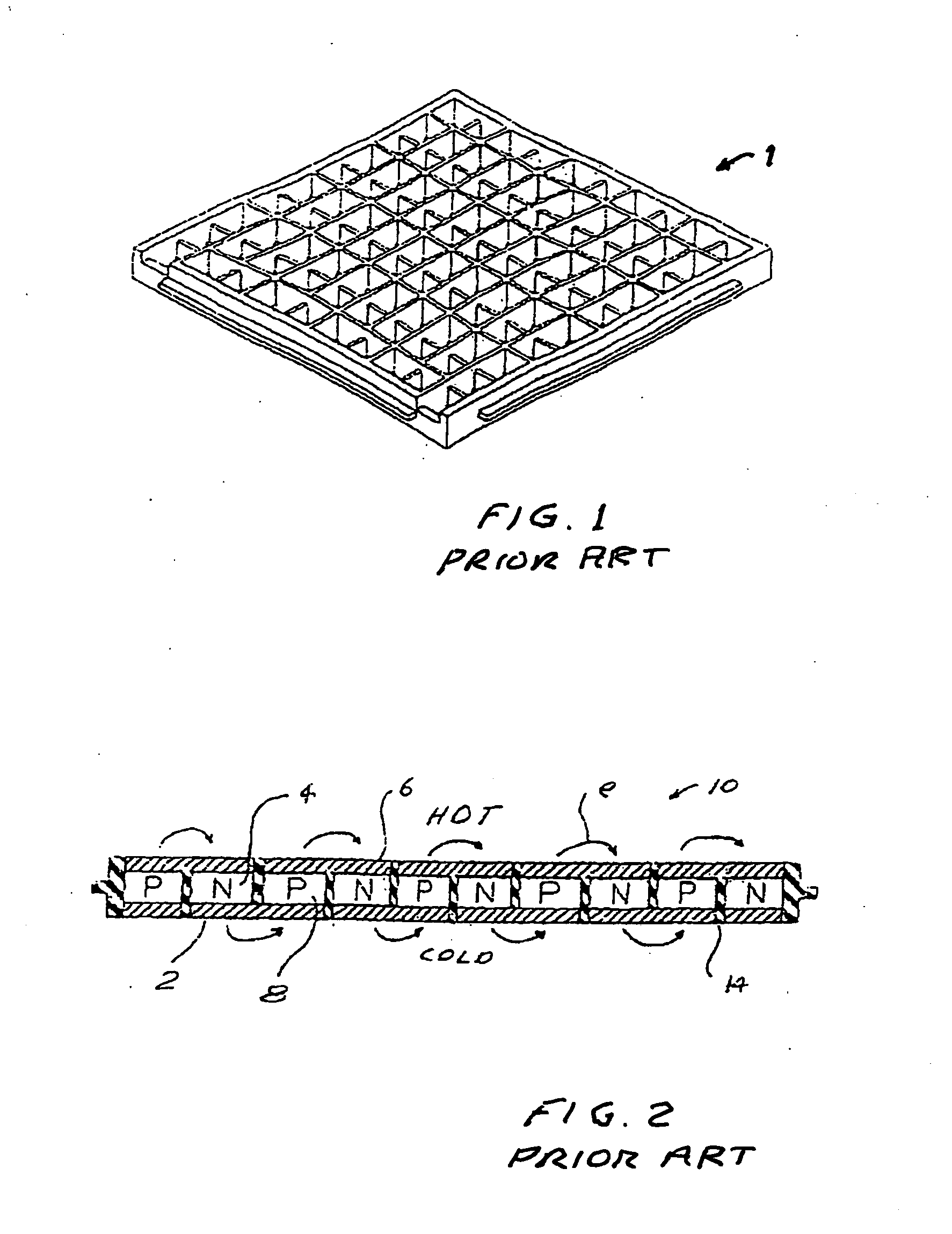
The reason primarily is that thermoelectric efficiencies are typically low compared to other technologies for electric power generation and the cost of thermoelectric systems per watt generated is relatively high compared to other power generating sources.
Mica, however, is marginal in strength and cracks easily.
That lead telluride module was suited for operation in temperature ranges in excess of 500° C. But the cost of fabrication of this prior art module is greatly in excess of the bismuth telluride module described above.
Also, after a period of operation of about 1000 hours some evaporation of the P legs and the N legs at the hot side would produce cross contamination of all of the legs which would result in degraded performance.

Method used


Image

  • Segmented thermoelectric module with bonded legs
  • Segmented thermoelectric module with bonded legs
  • Segmented thermoelectric module with bonded legs

Examples


first preferred embodiment

[0043]A first preferred embodiment can be described by reference to FIGS. 7 through 10C. FIG. 7 shows a P leg of this first preferred embodiment. At the top is a copper layer 90 on the hot end to aid in bonding to a copper conductor. Below copper layer 90 is an iron layer 92 to and a mixed layer 94 of 25 percent Fe and 75 percent P-type PbTe to chemically insulate the PbTe layer 96 from the copper layer 90. Below the PbTe layer 96 is a Bi2Te3 layer 98 and at the bottom is a thin layer of Fe 100 to enhance bonds with a later to be provided sprayed zinc connections. The thermoelectric material for layers 96 and 98 are chosen to provide high thermoelectric efficiencies at both the higher and lower temperature regions of the P leg. FIG. 8 shows a similar design for the N legs. At the top is a copper layer 102 and Fe and mixed layers 104 and 106 as for the P leg. The 3N layer 108 is a layer of PbTe designed for high efficiencies at temperatures close to 500° C. and the 2N 110 is a layer ...


PUM

PropertyMeasurementUnit
temperaturesaaaaaaaaaa
temperatureaaaaaaaaaa

Abstract

A segmented lead telluride egg-crate thermoelectric module. In preferred embodiments N legs and P legs are segmented into at least two segments. The segments are chosen for their figure of merit in the various temperature ranges between the hot side and the cold side of the module. In preferred embodiments a low-temperature egg-crate, molded from a liquid crystal polymer material, having very low thermal conductivity holds in place and provides insulation and electrical connections for the thermoelectric N legs and P legs at the cold side of the module. A castable ceramic capable of operation at temperatures in excess of 500° C. is used to provide electrical insulation between the legs at the hot side of the module.

Description

CROSS REFERENCE TO RELATED APPLICATIONS[0001]The present invention is a continuation-in-part of Ser. No. 12 / 317,170 filed Dec. 19, 2008 and Ser. No. 12 / 590,653, filed Nov. 12, 2009, both of which are incorporated herein by reference.FIELD OF THE INVENTION[0002]The present invention relates to thermoelectric modules and especially to mid temperature to high temperature thermoelectric modules.BACKGROUND OF THE INVENTIONThermoelectric Materials[0003]The Seebeck coefficient of a thermoelectric material is defined as the open circuit voltage produced between two points on a conductor, where a uniform temperature difference of 1 K exists between those points.[0004]The figure-of-merit of a thermoelectric material is defined as:Z=α2σκ,where α is the Seebeck coefficient of the material, σ is the electrical conductivity of the material and κ is the total thermal conductivity of the material.[0005]A large number of semiconductor materials were being investigated by the late 1950's and early 19...

Claims


Application Information

Patent Timeline
Patent Type & Authority Applications(United States)
IPC IPC(8): H01L35/32H01L35/20H10N10/17H10N10/854
CPCF01N5/025H01L35/34H01L35/32H01L35/30H10N10/13H10N10/01H10N10/17
Inventor LEAVITT, FREDERICK A.MCCOY, JOHN W.MARUDHACHALAM, PANNEERSELVAMGAERTNER, MARTIN
Owner BASF SE & HI Z TECH
Learn More