
Hybrid organic photodiode

Inactive Publication Date: 2012-05-17
SIEMENS HEALTHCARE GMBH
View PDF3 Cites 23 Cited by
  • Summary
  • Abstract
  • Description
  • Claims
  • Application Information

AI Technical Summary

Benefits of technology

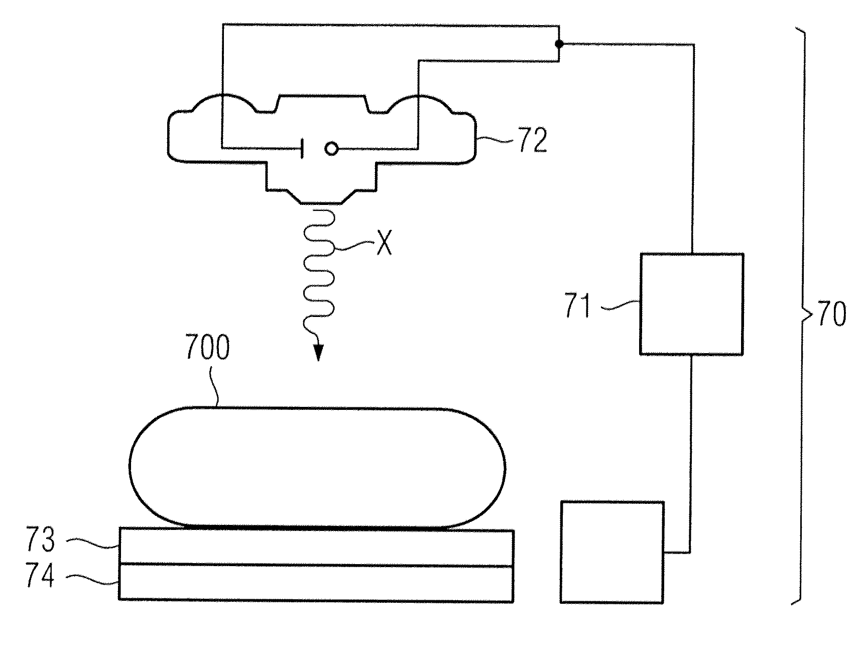
[0011]The x-ray detector according to the invention is designed for imaging and / or for dose rate measurement. The x-ray detector has a hybrid photoactive layer between a first electrode and a substrate. The first electrode is a cathode of the photodiode. The hybrid photoactive layer includes a number of scintillators as well as a bulk heterojunction. The photoactive layer is designated as a hybrid since, with the scintillators and the bulk heterojunction, it comprises two different converter materials. However these are not arranged in separate layers as has previously been known; rather they are combined into a single, photoactive layer. The scintillators serve to convert the x-ray radiation into scintillator radiation, in particular fluorescence radiation in the visible wavelength range. The bulk heterojunction is designed to absorb in precisely this wavelength range of the scintillator radiation and to thereby form electron-hole pairs. The hybrid photoactive layer (which has scintillators and a bulk heterojunction) is therefore designed to produce indirect x-ray conversion. Moreover, the x-ray detector is designed to electrically detect the electron-hole pairs that are generated in the bulk heterojunction. The x-ray detector according to the invention has the advantage of operating satisfactorily with a low component depth, with an individual hybrid photoactive layer between a first electrode and a substrate, and has a very simple structure. The x-ray detector according to the invention, moreover, accomplishes these features without highly toxic selenium. The hybrid photoactive layer is equally suitable to ensure an imaging or a dose rate measurement.
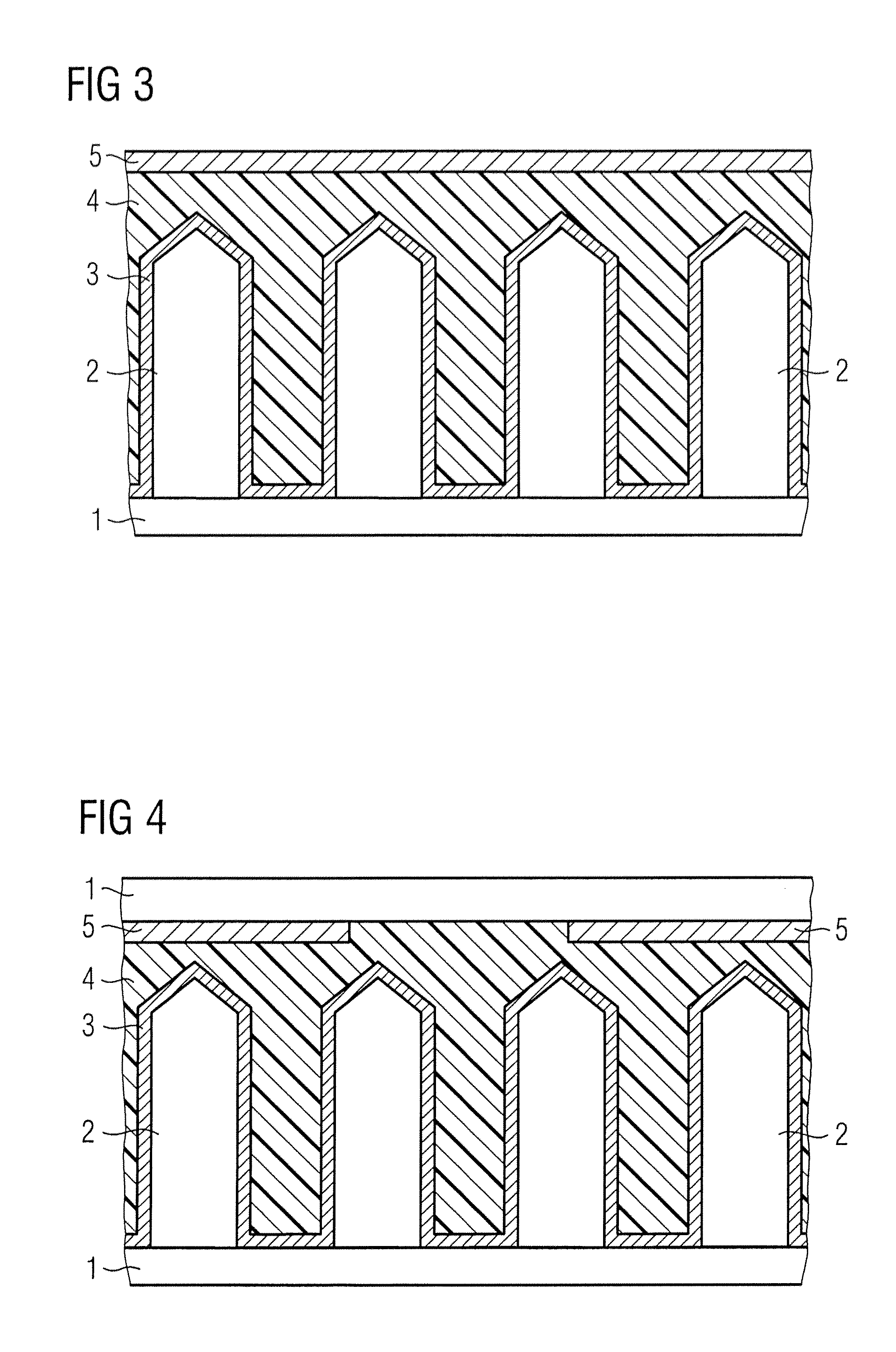
[0036]In addition to the hybrid photoactive layer, the x-ray detector thus comprises at least one first electrode and a substrate. The substrate can be a transparent substrate (for example a glass substrate) or can also be an active matrix backplane. A second electrode (for example the anode of the photodetector) can be applied on the substrate. The anode can in turn be transparent (for example can be a TCO, a transparent conductive oxide) that, for example, can be deposited via an ALD process. The anode can be composed of multiple anode pixels or can be continuous. One of the electrodes is appropriately the anode or the cathode made up of multiple pixels. For example, for the case of the embedded scintillator particles the hybrid photoactive layer can be arranged between the anode and the cathode. Interlayers that, for example, serve for charge separation can also be arranged between anode and cathode. However the anode can also be arranged between the scintillators and the bulk heterojunction if the bulk heterojunction was applied in the form of an ALD layer over the scintillator needles, for example. Accordingly, it is then not the anode that is pixelated but rather the cathode. In general, an inverse structure is also possible wherein the cathode is initially applied on the substrate and the anode is applied on the hybrid photoactive layer, but the design with a top cathode (that, for example, can be made of a metal) is advantageous. Aluminum, calcium-silver or calcium-gold electrodes are suitable metals for this top cathode. For example, such metal electrodes can be deposited via vaporization processes. In the case of thermal vaporization processes, a structuring of the top electrode can be produced by shadow masks.

Problems solved by technology

Selenium as an absorber is particularly disadvantageous due to its high toxicity.
Since scintillators made from cesium iodide are extremely hygroscopic, their use in combination with photodetectors is always linked with a structural cost (for example for a moisture protection encapsulation) and is disadvantageous to the service life of the x-ray detector.
Direct x-ray converters have previously been used for medical imaging, but those have significant component depths and therefore require high, energetically inefficient operating voltages in the kV range.
A disadvantage of known x-ray detectors is that they are suitable only for severely limited range of use.

Method used


Image

  • Hybrid organic photodiode
  • Hybrid organic photodiode
  • Hybrid organic photodiode

Examples


Embodiment Construction

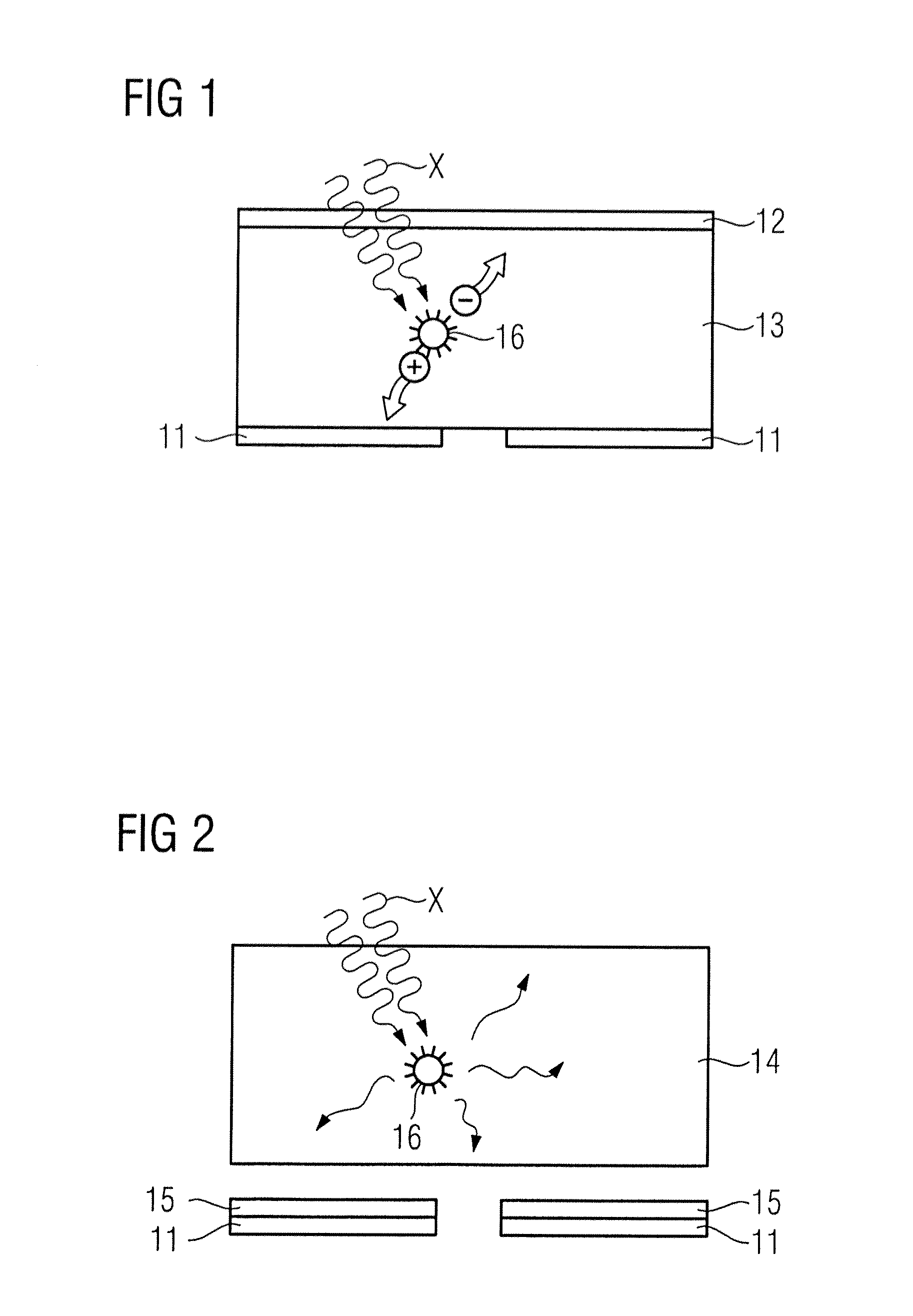
[0052]FIG. 1 shows an x-ray detector for direct x-ray conversion according to the known prior art. A material 13 that is suitable for absorption and direct conversion of x-ray radiation X is arranged between a pixel electrode 11 and a top electrode 12. The pixelation of the electrode 11 is produced for spatial resolution. The top electrode 12 is permeable to x-ray radiation X. The x-ray radiation X is absorbed in the material 13 to form an electron-hole pairs. In FIG. 1, the conversion center 16 is schematically shown in which the transduction of the radiation energy of the x-ray radiation X into electrical energy takes place in that the energy of the radiation is transferred to an electron and this is raised to a higher energetic state. The electron-hole pair that is formed in such a manner can be separated in an applied field that can be applied to the material layer 13 via the electrodes 11, 12. This means that the x-ray detector operates under a bias voltage and can detect a cur...


PUM

PropertyMeasurementUnit
Thicknessaaaaaaaaaa
Thicknessaaaaaaaaaa
Percent by volumeaaaaaaaaaa

Abstract

An x-ray detector that is suitable for both imaging and dose rate measurement has a hybrid photoactive layer arranged between an electrode and a substrate. The hybrid photoactive layer includes a number of scintillators as well as a bulk heterojunction and is designed to produce indirect x-ray conversion. The bulk heterojunction absorbs the scintillator radiation to form electron-hole pairs that are detected electrically. The production takes place by a spraying process, in particular a co-spraying process of bulk heterojunction solution and scintillator particle suspension.

Description

BACKGROUND OF THE INVENTION[0001]1. Field of the Invention[0002]The present invention concerns x-ray detectors based on indirect x-ray conversion.[0003]2. Description of the Prior Art[0004]In the field of x-ray detectors, there is a fundamental differentiation as to whether the x-ray detector is based on direct or indirect x-ray conversion. These forms of x-ray detection are shown in FIGS. 1 and 2, respectively and described below in detail.[0005]In direct x-ray conversion, the x-ray radiation is absorbed in a material and an electron-hole pair is generated with the energy of said x-ray radiation. The generated electron-hole pair can be read out electronically. Amorphous selenium is used as a material for this purpose, for example. Silicon diodes are also used for direct x-ray conversion. Direct x-ray conversion in a semiconductor depends on a certain layer thickness in order to absorb a sufficiently high proportion of the radiation for a detection. Silicon diodes for direct x-ray c...

Claims


Application Information

Patent Timeline
IPC IPC(8): G01N23/04C23C16/44B05D5/12B05D1/02G01T1/20B05D5/06
CPCG01T1/2018G01T1/023G01T1/20187G01T1/20189G01T1/20G01T1/02
Inventor HAYDEN, OLIVERRAUCH, TOBIASSCHULZ, REINER FRANZSRAMEK, MARIATEDDE, SANDRO FRANCESCO
Owner SIEMENS HEALTHCARE GMBH
Learn More