Compositions and methods for synthesis of hydrogen fuel

a hydrogen fuel and synthesis technology, applied in the field of hydrogen fuel compositions and methods, can solve the problems of poor conversion efficiency in solar cell applications, high cost of the manufacturing process, and inability to achieve similar attention to the brookite phase,

Inactive Publication Date: 2012-05-24
RGT UNIV OF CALIFORNIA
View PDF4 Cites 15 Cited by
  • Summary
  • Abstract
  • Description
  • Claims
  • Application Information

AI Technical Summary

Benefits of technology

[0015]In one embodiment the method herein disclosed comprises using a photon source wherein the photons from the photon source have power intensity of between 1 and 10000 mW / cm2. In a preferred embodiment the photons from the photon source have power intensity of between 10 and 1000 mW / cm2. In a more preferred embodiment the photons from the photon source have power intensity of between 25 and 250 mW / cm2. In a yet more preferred embodiment the photons from the photon source have power intensity of 100 mW / cm2. In an alternative more preferred embodiment the photons from the photon source have power intensity of 27 mW / cm2. For example, the photons from the photon source can have a power intensity of 1, 2, 2.5, 3, 4, 5, 6, 7, 8, 9, 10, 12.5, 15, 17.5, 20, 25, 27, 30, 35, 40, 45, 50, 55, 60, 65, 70, 75, 80, 85, 90, 95, 100, 110, 120, 130, 140, 150, 160, 170, 180, 190, 200, 250, 300, 350, 400, 450, 500, 550, 600, 650, 700, 750, 800, 850, 900, 950, 1000, 2000, 3000, 4000, 5000, 6000, 7000, 8000, 9000, 10000 mW / cm2 .
[0016]The invention also provides a method for generating hydrogen, the method comprising the steps of (i) providing a conducting substrate; (ii) doping a crystalline metal oxide with nitrogen; (iii) depositing said nanocrystalline metal oxide doped with nitrogen upon said conducting substrate; (iv) providing a semiconductor quantum dot; (v) linking said semiconductor quantum dot to said conducting substrate using a linker; (vi) providing a hydrogen source in contact with the opposing surface of said conducting substrate; (vii) irradiating the surface of said conducting substrate with a photon source thereby creating or inducing an electric current through the conducting substrate; (viii) allowing the electric current to electrolyze the hydrogen source, thereby producing hydrogen; the method thereby generating hydrogen. In a preferred embodiment the photon source is selected from the group consisting of a tungsten lamp, a fluorescent lamp, an arc lamp, a laser, a light-emitting diode, a liquid crystal diode, a radionuclide, the sun, a gamma ray, a fluorescent molecule composition, and the like. In one preferred embodiment the conducting substrate is selected from the group consisting of indium tin oxide and fluorine tin oxide. In another preferred embodiment the nanocrystalline metal oxide is selected from the group consisting of titanium dioxide, tungsten oxide, and zinc oxide. In yet another preferred embodiment the semiconductor quantum dot is selected from the group consisting of cadmium selenium and cadmium telluride. In a still further preferred embodiment the linker is selected from the group consisting of thioglycolic acid (TGA), mercaptopropanoic acid (MPA), and cysteine and links the semiconductor quantum dot with the conducting substrate. In a preferred embodiment the hydrogen source is a compound comprising hydrogen, carbon, oxygen, or any combination thereof. In a more preferred embodiment the hydrogen source is selected from the group consisting of methanol, ethanol, water, formic acid, and an amine compound. For example, the hydrogen source can be an alcohol, an organic acid, or an organic waste compound, such as residual waste from households, commerce, and / or industry.
[0017]In one embodiment the method herein disclosed comprises using a photon source wherein the photons from the photon source have power intensity of between 1 and 10000 mW / cm2. In a preferred embodiment the photons from the photon source have power intensity of between 10 and 1000 mW / cm2. In a more preferred embodiment the photons from the photon source have power intensity of between 25 and 250 mW / cm2. In a yet more preferred embodiment the photons from the photon source have power intensity of 100 mW / cm2. In an alternative more preferred embodiment the photons from the photon source have power intensity of 27 mW / cm2. For example, the photons from the photon source can have a power intensity of 1, 2, 2.5, 3, 4, 5, 6, 7, 8, 9, 10, 12.5, 15, 17.5, 20, 25, 27, 30, 35, 40, 45, 50, 55, 60, 65, 70, 75, 80, 85, 90, 95, 100, 110, 120, 130, 140, 150, 160, 170, 180, 190, 200, 250, 300, 350, 400, 450, 500, 550, 600, 650, 700, 750, 800, 850, 900, 30 950, 1000, 2000, 3000, 4000, 5000, 6000, 7000, 8000, 9000, 10000 mW / cm2 .

Problems solved by technology

Efficiency of silicon solar cells have attained a solar conversion efficiency of 20%, however the manufacturing process is very expensive and involves the use of toxic chemicals inherit in the semiconductor industry.
On the contrary, the brookite phase has not received similar attention, perhaps because it is the most difficult to prepare in the form of a thin film (Djaoued, Y.; Bruning, R.; Bersani, D.; Lottici, P. P.; Badilescu, S.
Titania has a wide band gap (3.2 eV) and absorbs only 5% of the solar spectrum, resulting in poor conversion efficiency in solar cell applications.
However, they are not ideal due to their weak absorption of visible light (Murphy et al. supra).
To date, both sensitization and doping of metal oxide nanostructures have been explored separately for solar energy conversion applications, yet little work has been done on combining the two approaches.

Method used


Image

  • Compositions and methods for synthesis of hydrogen fuel
  • Compositions and methods for synthesis of hydrogen fuel
  • Compositions and methods for synthesis of hydrogen fuel

Examples


example i

Experimental Sample Preparation

A. Materials.

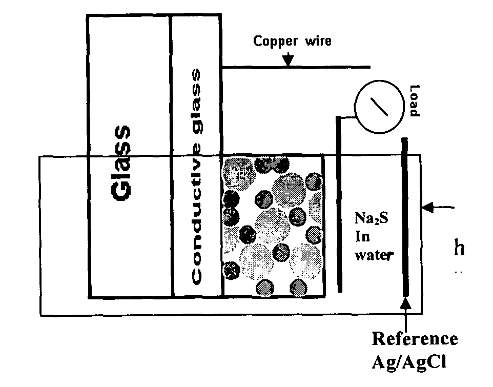
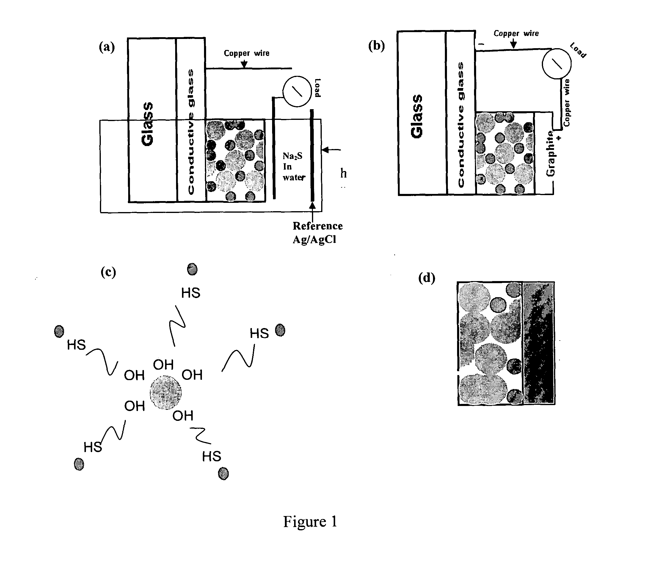
[0061]Titanium(IV) iso-propoxide (#377996, 99%), technical grade trioctylphosphine (TOP-#117854, 90%), trioctylphosphine oxide (TOPO #223301, 99%) , potassium chloride (KCl-#204099 , 99%), polyethylene glycol (PEG-#25322-68-3, average Mn ca. 10,000 g / mol) and sodium sulfide (Na2S-#407410, 99%) were obtained from Sigma-Aldrich (Milwaukee, Wis.). Cadmium oxide (CdO-#223791000, 99%) and selenium powder (Se 200 mesh-#198070500, 99%) were obtained from Acros organics (Morris Plains, N.J.). 1-tetradecylphosphonic acid (TDPA-#4671-75-4, 99%) was obtained from PCI synthesis (Newburyport, Mass.). Nitric acid (2.0N-#LC178502) was purchased from Lab. Chem Inc (Pittsburgh, Pa.). Thioglycolic acid (TGA-#103036, 98%) was obtained from MP Biomedicals Inc.(Solon, Ohio). F:SnO2 conductive glass (Tec glass 30 Ohms) was obtained from Hartford glass (Hartford City, Ind.) and the reference electrodes Ag / AgCl from CH Instruments Inc. (Austin, Tex.).

B. TiO2 Film...

example ii

Structural and Morphology Characterization

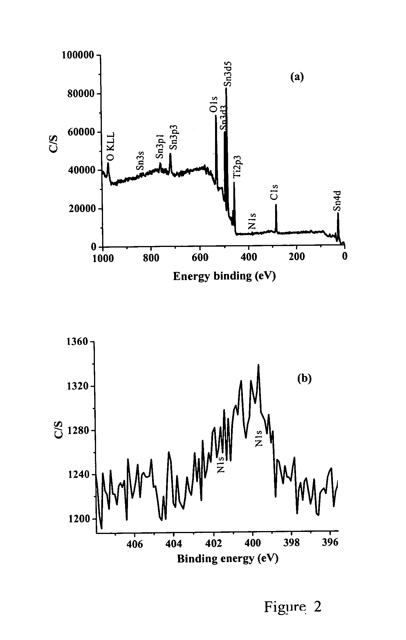
[0065]X-ray photoelectron spectroscopy (XPS) studies of the films were carried out on an X-ray photoelectron spectrometer (XPS, PHI Quantera SXM) using a non-monochromatized Al KR X-ray source (1486.6 eV). The energy resolution of the spectrometer was set at 0.5 eV. The binding energy was calibrated using a C 1s (284.6 eV) spectrum of a hydrocarbon that remained in the XPS analysis chamber as a contaminant. Crystalline phase identification was performed via X-ray diffraction (XRD) in conjunction with Raman spectroscopy. XRD analysis was conducted on a MINIFLEX diffractometer operating at 30 kV / 15 mA using Cu—Kα radiation and scanning speed of 1° 2θ / min.

[0066]Raman spectroscopy of the films was performed using a Renishaw micro-Raman setup with a (5 / 10 / 20 / 50)× objective lens and a 633 nm excitation wavelength. Renishaw's WiRE (Windows based Raman Environment) was used for collection and data analysis of 1 to 5 scans ranging in accumulations...

example iii

Optical and Electrochemical Characterization

[0069]UV-visible light (UV-vis) absorption spectroscopy was conducted on a Hewlett-Packard 8452A diode array spectrophotometer. UV-vis absorption spectra were measured first by placing a blank FTO glass substrate in the light path, subtracting the absorption pattern, and then performing the UV-VIS absorption measurement on the variety of TiO2 thin films.

[0070]Photoluminescence (PL) spectroscopy was gathered on a Perkin Elmer LS 50B with an excitation wavelength of 390 nm and 1% attenuator. QDs in toluene were placed in an open sided 1 cm path length quartz cuvette for both UV-vis absorption and PL measurements. Thin films were placed in a thin film sample holder from Perkin Elmer (#52123130) for PL spectra.

[0071]Photoelectrochemical studies (linear sweep voltammetry and incident photon-to-current conversion efficiency (IPCE) in solid state and in electrolyte were carried out with a CHI440 electrochemical workstation (Austin, Tex). Linear s...


PUM

PropertyMeasurementUnit
quantum efficiencyaaaaaaaaaa
thicknessaaaaaaaaaa
particle sizeaaaaaaaaaa

Abstract

The invention provides new methods and compositions for synthesizing hydrogen fuel using simple and inexpensive materials.

Description

[0001]This invention was made partly using funds from US Department of Energy (USDOE) research grant number DE-FG02-05ER46232-A002, and the United States National Science Foundation, Major Research Instrumentation (MRI) Program grant number CHE-0521569. The US Federal Government has certain rights to this invention.FIELD OF THE INVENTION[0002]The invention is drawn to novel compositions and methods for generating an electric current. The invention also provides novel compositions and methods for generating hydrogen as a fuel.BACKGROUND OF THE INVENTION[0003]In recent years there is an increasing interest to find sustainable alternative energy (SAE) sources due to the heightening cost of fossil fuels and the detrimental effects of global climate change. Photovoltaic (PV) cells have received significant attention due to the limitless influx of photons from the sun. Recent market energy analysis is predicting energy parity between conventional energy production and PV costs in cents pe...

Claims


Application Information

Patent Timeline
Patent Type & Authority Applications(United States)
IPC IPC(8): C25B1/02C25B9/04H01L31/0272H01L31/0224
CPCB01J21/063B01J27/0573C25B11/0405B01J37/10C25B1/003B01J35/004C25B1/55C25B11/051
Inventor ZHANG, JIN ZHONGWILCOTT, ABRAHAMHENSEL, JENNIFERLOPEZ-LUKE, TZARARALI, YAT
Owner RGT UNIV OF CALIFORNIA
Why Eureka
Try Eureka